EQ 1000
MOTORIZED WHEEL BALANCER WITH DIGITAL DISPLAY
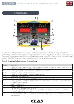
CONTROL PANEL
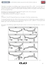
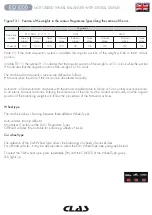
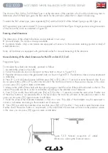
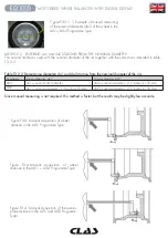
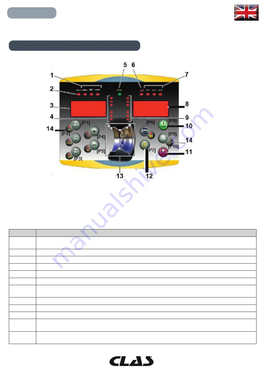
The machine control panel is shown in Figure F1. The control panel allows the operator to give commands
and enter or modify data. The same control panel displays the balancing results and machine messages. The
functions of the various sections of the control panel are described in table T1. The rear side of the control panel
contains the CPU-C1 electronic control board that collects, processes and displays data.
Table T1 Functions of different parts of the control panel
Position
Description
1
Indicator light for the selected CAR/MOT/SUV (Auto-vehicle/Motorbike/Off-road) Wheel Type. Group of three indi-
cator lights (red) indicating the Type of programme selected
2
Indicator light (red) for the selected unit of measure: inches (on) - mm (off ).
3 – 8
Display for viewing internal-external imbalance
4 - 9
Indicator light for the internal-external angular imbalance position
5
Active standby status indicator light
6
Enabling (on) - disabling (off ) indicator light of the automatic acquisition system of the wheel size
7
Indicator light for the selected Programme Type (Standard/Alu/Alu S). Group of three indi- cator lights (red) indicating
the Type of programme selected.
10
Start key to start the motor
11
Stop key to stop the motor
12
F key to access the secondary functions of the keys
13
Indicator light of the Weight Imbalance Position. Group of 7 LEDs (red). The position depends on the Type of Pro-
gramme and the Type of Wheel selected.
14
Example of standard key: it features a main function (indicated in the big circle) and a se- condary function (indicated
in the small circle)
F.1
Summary of Contents for EQ 1000
Page 29: ...29 EQ 1000 EQUILIBREUSE ROUES MOTORISEE AFFICHAGE DIGITAL ...
Page 75: ...NOTES ...

