OPERATION
3-22
DLV1280 DX
User’s Manual
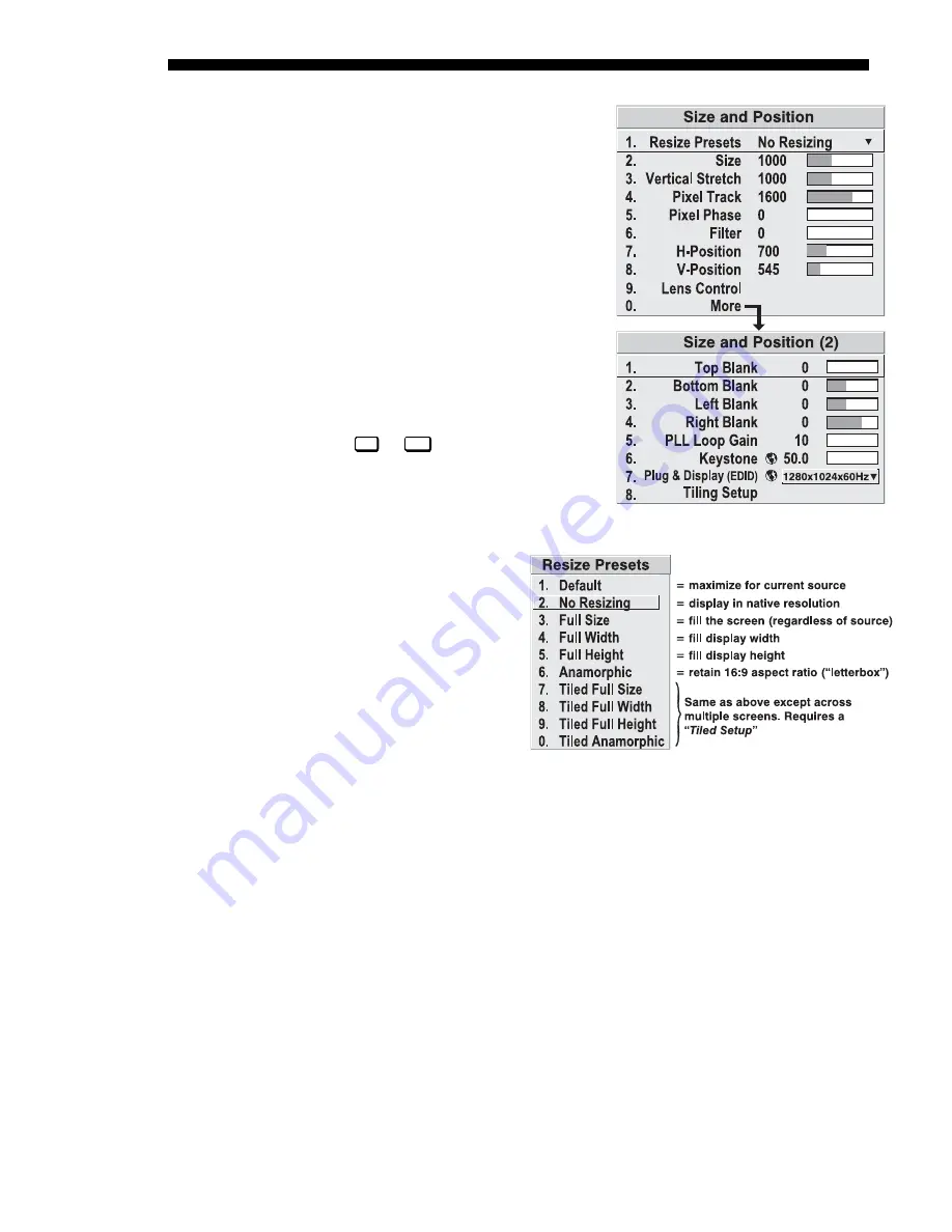
The Size and Position menu allows you to
increase or decrease the size of your
image, change its proportion (aspect
ratio), move the image to a specific area
of the screen, and refine other related
parameters. Use Size and Position
controls to match the image precisely to
the screen size and aspect ratio needed for
your application.
Refer to "Using Slidebars and Other
Controls" (earlier in this section) if you
need help using any of the following
slidebars or pull-down lists to alter your
image. Changes made to the Size and
Position menu are applied immediately
and are saved when you exit the menu
(press
Exit
or
Menu
).
Resize Presets
Use Resize Presets to quickly
display an image in its native
resolution (including
anamorphic) or to
automatically resize an image
to closely fit the screen. The
value for Size, Position and
Blanking parameters
(described later) will, in turn,
change as necessary without
your having to set them
manually. Resizing options
for non-tiled applications are explained in detail below.
WHAT IS THE PROJECTOR’S DEFAULT?
When displaying a new source, by default
your image will fill the screen as fully as possible for the type of source present. See
Select “Default” below.
WHEN “CUSTOM” APPEARS:
The “Custom” descriptor automatically appears in the
Size and Position menu when any of the values for Size, Vertical Stretch, H-Position,
V-Position or Blanking do not correspond to those for a preset. It is not an option in
the Resize Presets pull-down list.
•
SELECT “DEFAULT”
(default) for most images. This option will center and display
your image as large as possible for the present source as described below:
9
A graphic image will resize to fill the screen, regardless of its original
aspect ratio. For example, 1024 x 768 becomes 1280 x 1024.
9
A video image will resize to fill the screen while maintaining its aspect
ratio (assumed to be 4:3).
Image Size and Position
'
Figure 3.12. Size and Position Menu
Figure 3.13. Resize Presets Choices
Summary of Contents for DLV1280 DX
Page 95: ......
Page 111: ......
Page 122: ...Appendix B Keypad Reference DLV1280 DX User s Manual B 1 Figure B 1 Keypad ...
Page 123: ......
Page 124: ...Appendix C Menu Tree DLV1280 DX User s Manual C 1 ...
Page 125: ...MENU TREE C 2 DLV1280 DX User s Manual ...
Page 126: ...MENU TREE DLV1280 DX User s Manual C 3 ...
Page 127: ......
Page 129: ...SERIAL COMMUNICATION CABLES D 2 DLV1280 DX User s Manual ...
Page 130: ...SERIAL COMMUNICATION CABLES DLV1280 DX User s Manual D 3 ...
Page 131: ...SERIAL COMMUNICATION CABLES D 4 DLV1280 DX User s Manual ...
Page 133: ...THROW DISTANCE E 2 DLV1280 DX User s Manual ...
Page 139: ......


