background image

OPERATION

3-4

DLV1280 DX

 User’s Manual

The sensor on the projector will detect the signals and relay the commands for
internal processing.

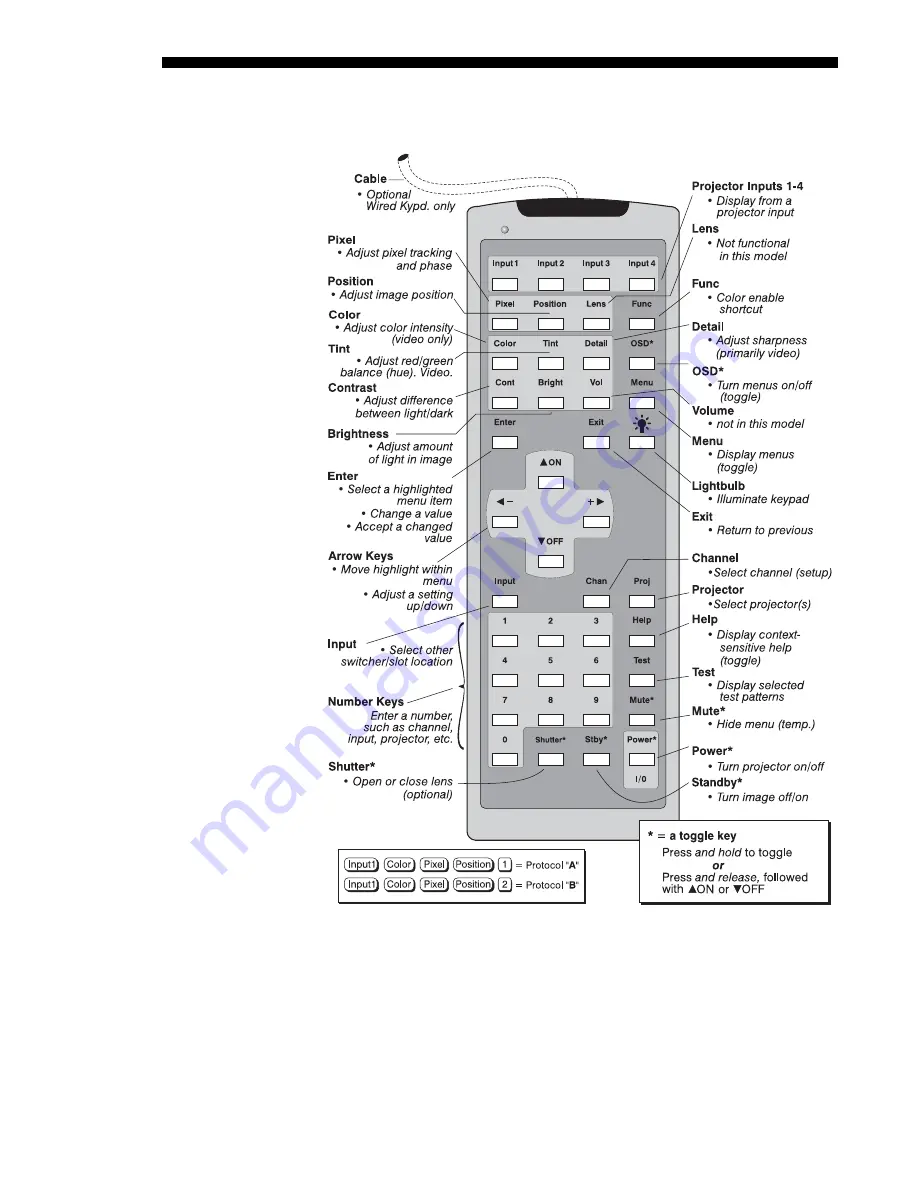
Figure 3.3. Keypad

The wired remote keypad connects to the 3-pin XLR jack via a 50 ft. cable. It is
recommended when:


the front of the projector is inaccessible


the lighting conditions are unsuitable for proper IR transmission


you want to use a separate keypad for each projector in a group

Wired Remote

'

—OPTIONAL—

Summary of Contents for DLV1280 DX

Page 1: ... 3 3 3 4 Navigating the Menus 3 11 3 5 Using Inputs and Channels 3 15 3 6 Adjusting the Image 3 21 3 7 Configuring System Parameters 3 37 3 8 Working With the Lamp 3 44 3 9 Projector Status 3 47 3 10 Using Multiple Projectors 3 47 3 11 Error Conditions 3 59 4 1 Warnings and Guidelines 4 1 4 2 Cleaning 4 3 4 3 Replacing Keypad Batteries 4 3 4 4 Replacing the Lamp and Filter 4 4 4 5 Replacing the Le...

Page 2: ...ndent vertical stretch for changing aspect ratios Choice of lamp modes for control of brightness and energy Standard short throw lens for image sizes from 5 to 30 feet diagonal Display of NTSC PAL and SECAM video input requires optional decoder Display from PCs VCRs laser disc players video cameras etc Memory for up to 99 custom channels Intuitive on screen menus or hidden direct control Remote ke...

Page 3: ... to service technicians for all projectors Should you encounter a problem with the projector and require assistance contact your dealer or the manufacturer In many cases any necessary servicing can be performed on site If you have purchased the projector fill out the information below and keep with your records In addition make sure to complete the Product Registration at the Christie website this...

Page 4: ...jector is level from side to side see 2 7 Leveling adjusting feet if necessary Connect a Source Locate the main input panel at the rear of the projector The lower left area labeled INPUT 1 accepts an RGB input via BNC connectors The upper right area assuming an optional video decoder is installed accepts a composite video at INPUT 3 or S video input at INPUT 4 Connect your source to the appropriat...

Page 5: ...80 DX delivers a high brightness high resolution output final display quality could be compromised if the projector is improperly installed This subsection discusses issues you should consider before proceeding with a final installation Even if you do not intend to use the projectors in a fixed and permanent installation this subsection will help you to better understand what you can do to enhance...

Page 6: ... the audience can see the display from various angles Because of the low gain flat screens are most effective when ambient lighting is reduced although this difference may be negligible given the high brightness output from this projector Figure 2 1 Audience Coverage with Flat Screen NOTE Lenses for this projector are designed primarily for use with flat screens but the projector depth of field ra...

Page 7: ... 1 aspect ratio For example to display a VCR output with a 4 3 aspect ratio onto a 10 foot 3m high screen the width of the screen must be at least 13 3 feet 4m Note Screen size is often specified as diagonal size Traditionally screens specified by diagonal size have aspect ratios of 4 3 Screens with other aspect ratios such as those recommended for this projector are not typically specified by dia...

Page 8: ...output of this projector is certainly well suited for locations where ambient lighting is less than optimum for projection yet there are still many simple things you can do to further optimize your installation Visiting a movie theater can give you an idea of what makes an ideal projection environment Walls floors and furnishings are dark and matte finished A projection room should not have white ...

Page 9: ...ight from the projection screen should be absorbed by the ceilings walls and floors so that it will not be reflected back to the screen Again keep reflective surfaces to a minimum Here are some other considerations and tips which can help you improve your installation Ventilation is an important factor when preparing a projection room The ambient temperature should be kept constant and below 35 C ...

Page 10: ...two examples of how audience coverage is maximized Figure 2 7 Screen Locations for Maximum Audience Coverage Installation type screen type and lighting all affect where the projector is positioned In addition both throw distance the distance between the projector and screen and vertical position the height of the projector in relation to the screen must be determined for every new installation Bot...

Page 11: ...zed Ideally the DLV1280 DX lens should be centered with the screen If necessary the image can then be manually offset that is moved up down or left right by making a slight mechanical adjustment to the lens mount essentially repositioning the lens within the projector WARNING Qualified service technician required To offset the image Figure 2 9 1 Center the lens with the screen as well as possible ...

Page 12: ...ove or below the lens center The maximum horizontal adjustment of 50 pixels means that up to 54 of the image can be projected to one side of the lens center Keep in mind that precise offset ranges depend on the specific lens you are using where the true lens center is located without offset and whether or not you are offsetting both horizontally as well as vertically See Table 2 1 and Figure 2 10 ...

Page 13: ...xels Amount of Image Offset from Lens Center Vertical Offset 70 pixels 57 i e 582 pixels Horizontal Offset 50 pixels 54 i e 690 pixels Figure 2 10 Vertical and Horizontal Offsets NOTES 1 If you cannot raise or lower the image enough using mechanical vertical offsets try adjusting V Position in the Size and Position menu see 3 6 Adjusting ...

Page 14: ...te that projector can be rotated and mounted at any vertical angle i e you can tilt the face of the projector up or down as much as desired for your installation The side to side tilt however must not exceed 15 see Figure 2 11 This limit ensures that the arc lamp in the projector operates properly and safely Always make sure that exhaust air from the projector does not vent towards the lens otherw...

Page 15: ...ource or it can also be used for YPbPr signals or additional video sources The upper right panel the optional Video Decoder Module accepts only composite video at INPUT 3 or S video at INPUT 4 from devices such as VCRs laser disk players or DVD players There are also several other optional interfaces available for connecting an additional source at INPUT 2 Such an option installs in the upper left...

Page 16: ...and blue source outputs to the RED GREEN and BLUE BNCs on the INPUT 1 panel If the source uses sync on green only the red green and blue connections are required If the source provides a composite sync output connect it to the SYNC input labeled HOR COMP If the source provides separate horizontal and vertical sync outputs connect horizontal sync to the SYNC input labeled HOR COMP and connect verti...

Page 17: ... as YCbCr to INPUT 1 Use the appropriate digital interface installed at INPUT 2 The video decoder input panel provides simultaneous connection of both a composite video source INPUT 3 and an S Video source INPUT 4 If connecting a composite video source use the Composite BNC connector or the RCA phono jack at INPUT 3 do not use both as inputs See Figure 2 15 NOTE If you want to loop a composite sig...

Page 18: ...3 and an S Video source INPUT 4 If connecting an S Video source use the 4 pin mini DIN connector or the Y and C BNC connectors luma and chroma at INPUT 4 do not use both as inputs See Figure 2 16 Figure 2 16 Connecting S Video NOTE If you want to loop an S video signal through to another projector or display device see Video Loop Through below S Video ...

Page 19: ...ext display device or projector Continue this looping method for each projector using either the phono plug or the adjacent BNC as input into INPUT 3 then using the other connector as an output i e loop through Whether you use the BNC or the phono plug as input or output depends on the type of cable you have on hand and what type of connectors are on each end VIDEO TERMINATION In the Video Options...

Page 20: ... type of cable you have on hand and what type of connectors are on each end VIDEO TERMINATION In the Video Options submenu make sure Video Termination is checked for only the final projector All other projectors must have this option unchecked in order for the signal to continue For other types of display devices in the chain typically a Hi Z switch position is needed Figure 2 18 Connections for S...

Page 21: ...needed or recommended 4 See Appendix F Optional Input Modules for a brief description of each interface You may wish to use one or more external Marquee Signal Switchers or a third party switcher in order to significantly increase the number of sources you can select If you are using a Marquee Signal Switcher connect the switcher s RGB output to INPUT 1 and connect an RS 232 serial communication c...

Page 22: ... source must be capable of supplying 860 watts of power to the projector See Section 5 Specifications for all power requirements WARNING Do not attempt operation if the AC supply and cord are not within the specified voltage and power range Caution Once the projector is turned off the lamp cooling fans will continue to run for approximately five minutes to ensure that the projector and lamp have s...

Page 23: ...full details Lens offset ranges are also listed on page 5 1 Further display adjustments are available through keypad commands and on screen menus refer to Section 3 Operation NOTE Communication software is required for serial control Contact your dealer for details You may wish to use equipment other than the keypad for controlling the projector or for performing other special functions Such equip...

Page 24: ... with RS 232 connecting one to the other could damage the equipment at either end If you wish to control the projector with a computer and or other controlling device such as the Two Way Controller having RS 422 capability connect RS 422 serial communication cables between the computer or other device and either or both of the projector serial ports labeled RS 422 these 6 pin XLR connector ports a...

Page 25: ...ER refer back to Figure 2 20 The switcher communication link permanently set at 9600 baud enables you to access inputs connected to the switcher in the same manner as those connected directly to the projector For most other third party switchers connect and access sources according to the documentation provided with that switcher NOTE See 2 4 Source Connections Connecting a Switcher for complete d...

Page 26: ...omputer controller having an RS 422 interface first set them all to the same baud rate needed then chain the projectors together by connecting the RS 422 PORT 2 connector of the first projector already connected to the computer controller to the RS 422 PORT 1 connector of the next projector in the chain Figure 2 25 Adding Another Projector via RS 422 ...

Page 27: ... such as baud rate must be set to match the particular controlling device before connecting as a network refer to the documentation that came with your controlling device in order to determine the proper baud rate See 3 7 Configuring System Parameters if you need help changing the projector baud rate from its default of 19200 NOTES 1 To avoid damage connect only properly wired serial communication...

Page 28: ...Whenever downloading new projector software to networks use a single route network only DISCONNECT any redundant serial cabling and UNCHECK the Split Network checkbox for each projector Two Different Splits There are two different split network configurations possible Figure 2 28 Set up whichever option best suits your application needs A SPLIT NETWORK WITH ONE CONTROLLER If you have a single cont...

Page 29: ...working with multiple linked projectors enabling you to direct commands to a certain projector rather than always broadcasting to the entire network For complete information on how to assign projector numbers see 3 7 Configuring System Parameters NOTE To loop a single incoming video source through to another projector or display device on a network see Video Loop Through in 2 4 Source Connections ...

Page 30: ...ugh a setting in the Communications menu See 3 7 Configuring System Parameters for further information on how to change the projector s infrared sensor protocol A protocol for either type of remote keypad IR or wired can be changed through software commands entered on the keypad A new protocol set through software commands remains in effect until the keypad batteries are removed and replaced if an...

Page 31: ...R or wired optional Use tweezers or needle nose pliers to remove and replace each jumper as necessary J1 jumper For either remote set between pins 1 and 2 to set as Protocol A Set between pins 2 and 3 to set as Protocol B J2 jumper For either remote set between pins 2 and 3 as shown otherwise the projector will not respond correctly to keypad commands J3 jumper For the IR remote make sure that the...

Page 32: ...commands again Press Input1 Color Pixel Position Protocol A Press Input1 Color Pixel Position Protocol B NOTE If you change a keypad to a new protocol and the projector stops responding the projector is likely set to a conflicting protocol To regain use of the keypad either change the keypad protocol back again or use the opposing type of keypad IR or wired as the case may be to access the Communi...

Page 33: ...t keypad protocol as desired using wired jumper settings Replace battery compartment cover Plug into the 3 pin XLR port at the rear panel of the projector TO CHANGE FROM WIRED TO INFRARED Unplug the keypad from the projector Open the keypad back and unplug the keypad cable Wait 1 2 minutes Install batteries see Section 4 Set keypad protocol as desired using IR jumper settings Replace battery compa...

Page 34: ...jector functions and adjustments are entered through keypad commands that either control the projector directly or activate a system of intuitive menus Variations in settings can be defined and retained in the projector s internal memory as a custom channel with up to 99 different channels possible Components and functions are illustrated below Figure 3 1 Basic Projector Components ZOOM Accessed m...

Page 35: ...omposite video and S Video signal from devices such as VCRs RGB INPUT Accepts RGB and sync signals from devices such as computers as well as composite video S Video or YPbPr component signals RS 232 SERIAL INTERFACE WITH LOOP THROUGH Allows one or more projectors to be remotely controlled by a computer or controller and provides a communications connection for the Marquee Signal Switchers RS 422 S...

Page 36: ...AD CONNECTOR 3 pin XLR For optional tethered remote control of the projector HARD RESET Emergency access for powering down the projector in the event of a system failure Insert a pen point or small screwdriver The keypad appears in two locations Infrared IR Remote for tetherless control up to 100 feet away Wired Remote optional tethered to the rear of the projector While either keypad is identical...

Page 37: ...rnal processing Figure 3 3 Keypad The wired remote keypad connects to the 3 pin XLR jack via a 50 ft cable It is recommended when the front of the projector is inaccessible the lighting conditions are unsuitable for proper IR transmission you want to use a separate keypad for each projector in a group Wired Remote OPTIONAL ...

Page 38: ...rating at presentation level such as an image from the most recently used source signal The projector temporarily leaves presentation level whenever you use the keypad to work with control settings display menus or on line help For example pressing Menu after startup displays the main menu presentation level is no longer active although the image still appears in the background Press Menu again or...

Page 39: ...back See Menu Preferences later in this section Channel Press Chan to select a specific source setup channel defined and stored in projector memory Once you enter a 2 digit channel number or if there is a list displayed highlight it and press Enter the display will automatically change and update according to the numerous setup parameters defined for that channel NOTE Chan key behavior during a pr...

Page 40: ... conjunction with certain toggle keys i e those including an asterisk symbol to ensure a toggle only in the desired direction When turning the projector on for instance you may be too far from the projector to know whether it is really off or if the shutter is merely closed If you press Power and hold it for approximately 1 second in hopes of turning the projector on the projector will actually tu...

Page 41: ... to increase or decrease the amount of black in the image Use and until you reach the desired level of contrast for best results start high and decrease so that dark areas do not become black i e are crushed Conversely overly high brightness changes black to dark gray causing washed out images See 3 6 Adjusting the Image Image Settings subsection Volume This key is not functional in this projector...

Page 42: ...stalled press and hold Shutter for approximately 1 second to toggle the shutter closed or open with a single key press this also blanks the image electronically Or quickly press and release Shutter and follow immediately with ON or OFF if you want to guarantee the correct toggle useful if you are unsure of the present status Close the shutter whenever you want to mute all display yet maintain acce...

Page 43: ...ailed information about any current menu and highlight Press Help again to exit From presentation level press Help to access the General Help menu consisting of Using Help Setup Keys Source Input Selection Status Pwr LEDs and Using 3D Press Exit to leave General Help and return to presentation level Test Press Test to display one of the available test patterns Press Test again to display the next ...

Page 44: ...e desired option Extra long menus have a scroll bar on the right use the arrow keys to see the remainder of the menu Items that are locked or do not pertain to the current action or projector appear dimmed and cannot be selected NOTES 1 If there is no signal present all source dependent adjustments are disabled 2 After 15 minutes of inactivity the projector leaves the menu system and returns to th...

Page 45: ...e function menu Enter the menu option number corresponding to the setting you wish to change for example press to select Vertical Stretch in the Size Position menu Or move the highlight to the desired parameter and press Enter Or move the highlight to the option desired and press or Or bypass the menus entirely and use a single key to immediately access an adjustment during your presentation note ...

Page 46: ...e listed below LIST OF DIRECT SLIDEBARS H Position or V Position Position Pixel Tracking or Phase Pixel Volume Contrast Cont Brightness Bright Color Color Tint Tint Detail Detail Use the arrow keys to adjust a direct slidebar or press Enter and enter a specific number from the keypad then Enter or or to save or Exit to cancel When you are done press Exit to save and return to your presentation NOT...

Page 47: ...r to activate its adjacent edit window Any previously entered text is displayed with its first character highlighted in a square cursor signifying that this character is ready for editing NAVIGATE WITHIN THE EDIT WINDOW Press to move the cursor forward or to move the cursor backwards as desired EDIT A CHARACTER To edit a highlighted character use and to scroll through the alphabet numbers spaces a...

Page 48: ...se a wide variety of customized setups rather than having to repeatedly re configure the projector for different presentations Each physical source i e input can have several different channels associated with it INPUT An input simply describes a physical location for an incoming signal connection These connections are always either on the projector itself one of the four inputs at the rear of the...

Page 49: ...ers such as brightness contrast tint size etc in order to customize and optimize the display coming from a particular source For example the display settings you choose for a VCR source may be very different from those you choose for a high resolution computer source or one signal may simply vary from another signal used earlier through the same input location Once you have adjusted a display para...

Page 50: ...nnel List or if this channel is not displayed in the list the first channel in the list is highlighted 2 Channels created automatically do not appear in the Channel List unless a parameter has been changed All available channels are listed in the Channel Setup menu which describes how each channel can be accessed and which serves as the gateway for editing copying and deleting channels From the pr...

Page 51: ...put E3G European Tri Level on green Dig Digital FUNCTIONS WITHIN THE CHANNEL SETUP MENU To copy delete or edit any of the channels listed in the Channel Setup menu highlight the desired channel and do one of two things Press Func if you want to copy the selected channel or delete this or other channels See Copying or Deleting a Channel below Press Enter if you want to edit channel setups i e non i...

Page 52: ...ase the current channel will remain but will be redefined from projector defaults NOTE For any deletion a confirmation box appears to make sure that you really want to delete Select Cancel default if you don t want to delete after all The basic setups that describe how and where a channel can be accessed are listed in the Channel Setup menu These channel setups can be edited at any time in the Cha...

Page 53: ...e disabled If unchecked default all available image settings can be adjusted as desired You cannot use Auto Setup with a locked channel IN MENU If checked default except for automatically defined channels with unchanged parameters this defined channel will then appear in the list available when Chan key is pressed If unchecked the channel must be accessed via Chan on the keypad or via the Auto Sou...

Page 54: ...for certain options you may prefer to use a direct key from presentation level to go directly to a particular option rather than traveling through the menu system at all note this is not available for all display parameters For example press Cont to access the contrast slidebar immediately Press Exit to return to your presentation NOTES 1 To hide the direct slidebars only make sure the Display Sli...

Page 55: ... later will in turn change as necessary without your having to set them manually Resizing options for non tiled applications are explained in detail below WHAT IS THE PROJECTOR S DEFAULT When displaying a new source by default your image will fill the screen as fully as possible for the type of source present See Select Default below WHEN CUSTOM APPEARS The Custom descriptor automatically appears ...

Page 56: ...n All Size Vertical Stretch H Position V Position or Blanking values will change accordingly For example for a source with a native resolution of 800 x 600 No Resizing will center a small image within a black border Conversely an HDTV image is wider than 1280 and will be cropped on the sides or in the case of 1080i HDTV cropped at top and bottom too With No Resizing signals with non square pixels ...

Page 57: ...oportion of data from the incoming signal Vertical Stretch Vertical stretch adjusts the height the image while keeping the width constant Use Vertical Stretch to display data from the incoming signal in a different aspect ratio Pixel Track SHORT CUT Press Pixel and adjust the top slidebar Pixel tracking adjusts the frequency of the pixel sampling clock indicated by the number of pixels per line so...

Page 58: ... and phase the image still appears noisy adjust Filter as described below Filter This option applies a low pass filter to the input signal Filter removes high frequencies which can improve pixel phase noise but which also reduces signal bandwidth Note that most signals will not require any filter adjustment use the filter option only if standard pixel tracking and phase adjustments do not adequate...

Page 59: ...ing of 10 is set automatically with a Pixel Tracking adjustment and is correct in most cases In rare instances such as if your image exhibits tearing or flag waving increase the PLL loop gain setting as necessary Or if your image is unstable and breaks up this may indicate that the PLL loop gain setting is either too high or too low PLL Loop Gain affects the current channel only Keystone Not avail...

Page 60: ...ght areas do not become white i e are crushed For best results keep close to 50 NOTE If environment lighting changes it may be necessary to re adjust both options Brightness SHORT CUT Press Bright and adjust the slidebar Brightness increases or decreases the amount of black in the image 0 100 Start high and decrease so that dark areas do not become black i e are crushed Conversely high brightness ...

Page 61: ...cognize them as RGB and will incorrectly decode their color information as YPbPr video These signals can include RGB signals in NTSC PAL SECAM frequency ranges Scan doubled sync on green Scan quadrupled sync on green For these signals change the Color Space to RGB then define a new channel for future use Color Setup Select this submenu to work with aspects of color adjust for saturation and overal...

Page 62: ...nt of signal input between minimum black and maximum white Different curves can improve performance for certain kinds of source input and applications Generally the best gamma curve is one that produces maximum contrast brightness and color performance for the current signal and ambient lighting conditions DEFAULT default This setting provides good black levels and high contrast under optimum view...

Page 63: ...enu is described below NOTE For best results use an internal grayscale test pattern when working with color temperature Figure 3 15 Color Temperature Setup Menu SELECT COLOR TEMP See Figure 3 15 Upon opening the Color Temperature Setup menu the current temperature appears as the top option You can change to a different color temperature here as desired just as in the Image Settings menu Note that ...

Page 64: ...replace the currently selected User color temperature setup with that of another This function can be particularly useful as a starting point for a new User color or for accessing an unaltered factory default It is disabled for all color temperatures except User See Figure 3 16 Figure 3 16 Copy From To create a starting point To set a starting point for a new custom user color temperature select a...

Page 65: ...ances EXCEPT 1 a poor quality input signal or 2 a black and white video signal In order to detect and display such signals select the relevant standard INPUT VIDEO BLACK This control compensates for incoming elevated black levels called setup that are present in certain video signals and ensures that blacks on screen are neither crushed i e with dark gray appearing black nor excessively elevated i...

Page 66: ...es input levels for all but the most unusual of sources 2 Before attempting an input level adjustment check that overall contrast and brightness settings are near 50 and that color temperature is properly set up on an internal grayscale test pattern 3 There must be at least one white pixel present in the image for proper Auto Input Level function Leave this control off Good RGB or input levels tha...

Page 67: ...Temporarily enable Auto in the Input Levels submenu Wait for all 6 values to stabilize Alternatively do not use Auto reduce blacklevels manually instead Judge by eye and change one or more of the six levels as necessary to obtain proper blacks and whites You may want to see only a certain color while adjusting use the Color Enable option described below 6 Delete the Auto checkmark and leave the In...

Page 68: ...ray field before adjustment 2 Display one primary color use Color Enable to select 3 For the current color adjust its corresponding Blacklevel slidebar just until a single band of black appears at one edge of the screen This band represents the first band of the grayscale pattern which should be 100 black Do not adjust too far 4 With the same color still active adjust its corresponding Input Drive...

Page 69: ...fore routing through the ADP module Motion Filter This control is most useful for smoothing out moving images from interlaced sources In most cases the proper Motion Filter setting is automatically determined according to the type of incoming source signal However if your source is noisy and or inconsistent you may wish to force a setting to ensure stable processing for this source if desired over...

Page 70: ...along vertical edges Vertical Filter requires optional ADP Module Select the amount of vertical filtering desired for the current source Note that the default setting of 0 allows the projector to optimize the amount of vertical filtering according to the current source and is the recommended setting for most situations You can override this by selecting a value from 1 10 with 1 applying no filteri...

Page 71: ... a checkmark if you want to see a scrollable channel list whenever you press Chan from your presentation These channels must be marked with a list icon in the Channel Setup menu This option also enables on screen feedback when using the Input key If you prefer to hide the channel list and input dialog box while switching channels and sources during a presentation do not enter a checkmark NOTE The ...

Page 72: ...t all display areas This submenu is typically used only in multiple projector applications that require precise matching between adjacent displays COLOR TEMP SETUP See Image Settings This function is offered in multiple menu locations for convenient access ADJUST PRIMARY COLORS This feature sometimes called color space conversion enables precise matching of color hue and intensity in multi screen ...

Page 73: ...gging the projector during operation Note that unsaved display adjustments may be lost Diagnostics and Calibration From the Diagnostics and Calibration submenu you can access several options for testing and setup of images You can work with test patterns and specific colors freeze an image for inspection and or access the Odd Pixel Adjustment menu for precision settings of offset and gain TEST PAT...

Page 74: ... to work with factory defined color temperatures and other functions This submenu is password protected and intended for use by qualified service technicians only Use the checkboxes and pull down lists in the Communications submenu to alter the methods or types of communication to and from one or more projectors NOTE Changes made to the Communications submenu will be saved upon exit of the menu Ba...

Page 75: ...er right corner of the rear projector panel Wired Keypad Like the IR remote keypad the optional wired keypad is either a Protocol A keypad manufacturer s default or a Protocol B keypad Likewise the projector can be set to accept wired keypad data accordingly responding to A or B If desired you can prohibit the projector from responding to a particular wired keypad protocol or you can ensure that t...

Page 76: ...ector application see key description in 3 3 Using the Keypad If you make a mistake in assigning or changing the projector number press Exit to cancel For complete information about controlling multiple projectors see Section 3 8 Split Network NOTES 1 Requires double serial links RS 232 and RS 422 between all projectors in a network 2 Set each projector s Broadcast Key OFF 3 Keypads cannot broadca...

Page 77: ... a new lamp serial number this read only value automatically resets to 0 where it begins to log time for the new lamp Lamp Hours also appears in the Status menu LAMP S N is the serial number recorded for the current lamp When you install a new lamp and enter its serial number the read only number will appear here Enter a checkmark for LAMP MESSAGE if you want to enable a warning message upon power...

Page 78: ...imply always need as much brightness as possible choose Max Brightness Lamp modes are described below Max Brightness The lamp will always burn as brightly as possible driven by maximum power of 500W in this model Keep in mind that the maximum brightness for any lamp gradually diminishes with age the image will become dimmer over time Its current output level appears in the Intensity option not in ...

Page 79: ... to dim as usual even though your original Intensity value will still appear in the menu To resume accurate tracking reduce the intensity setting so that the resulting Power value is less than its maximum the lower the intensity the longer it can be maintained Do not lower the Intensity so much that the corresponding Power value reaches its minimum 350 watts in this model the intensity setting wil...

Page 80: ... number In addition the Status menu identifies the current channel switcher slot and frequencies Use ON OFF or to see additional Status information Figure 3 27 Status Menu SAMPLE When working with multiple projectors you may want to use the RS 232 or RS 422 serial ports to chain the projectors together in a network that you control from either a keypad or a computer controller see 2 9 Serial Port ...

Page 81: ...to issue commands use the correct RS 232 software command to gain control of a single projector First make certain that only one projector has its Broadcast Keys option selected checked the remaining projectors must have the option unchecked and their keypads disabled do this in Communications submenu The Broadcast Keys projector will then relay keypad commands to the others If using a wired remot...

Page 82: ...tions of incoming data will then automatically map to the appropriate row column address in your videowall filling the wall with a complete image that is scaled as you have specified NOTES 1 Tiled resizing options are enabled only if you have defined an array of two or more projectors as described above 2 Use the same tiled resizing option for each projector in your array regardless of the number ...

Page 83: ...edges of the wall See right NOTE FOR LARGE ARRAYS 1 In large arrays having 3 or 4 columns rows the center screen s will automatically fill 2 Screens having very little or no image will be blanked cropped For each projector select Tiled Anamorphic to fill the videowall from left to right while maintaining the incoming widescreen anamorphic aspect ratio of 16 9 This typically creates a black border ...

Page 84: ... you can ignore color temperature at this point since it will be redefined when adjusting primary colors but do set up the projectors in every other aspect Also make sure that edges of adjacent screens are very close to one another 1b ASSIGN PROJECTOR NUMBERS Make sure each projector is assigned a unique 3 digit number see Assigning a Projector previous page You ll then be able to switch between c...

Page 85: ...ar grayed out in the menu In addition full normal adjustment of Gamma is regained 2b SELECT A USER COLOR TEMPERATURE User 1 RECOMMENDED In the Adjust Primary Color CSC menu select a User color temperature that you will be defining through your adjustment of primary colors on each projector Choose any of the four User choices but note that User 1 is the default color temperature applied if you add ...

Page 86: ...reen fields and choose the dimmest In the Green Primary menu for each remaining projector reduce the Green White Level as necessary until all green light output appears to match See right 3c MATCH GREENS Compare green fields and choose the least saturated green i e the screen which you feel is furthest from pure green and leans slightly toward yellow or blue In the Green Primary menu for each rema...

Page 87: ...o the Achieving Brightness Uniformity procedure provided below Applying the Primary Color Adjustments For New Sources For any new sources that you may use keep in mind the following User 1 is the default color temperature for all sources as long as the Use Primary Color Adjustment checkbox remains checked in the Adjust Primary Colors CSC menu 6500K is the default color temperature if you adjusted ...

Page 88: ... as described in the Matching Colors in Multiple Screens procedure above before attempting to work with Brightness Uniformity This ensures that primary colors color temperature and maximized light output are all well matched from one screen to another These matches are needed before you can achieve good Brightness Uniformity results With a new lamp review primary colors before working with Brightn...

Page 89: ...lors see Matching Colors in Multiple Screens for this procedure This ensures matched overall color temperatures and light output between screens IMPORTANT Double check that all WHITES and LIGHT OUTPUT are well matched See Step 3f of the Matching Colors in Multiple Screens procedure Use a color meter if necessary 1b Enable the Brightness Uniformity checkbox This will enable access to the uniformity...

Page 90: ...ess of individual zones 2 Always ignore menu colors 2a On each screen compare the color temperatures in the 8 target zones 4 edges and 4 corners to that of the color temperature of the center Compare using a white field only and take note of any areas that do not match the center Also decide if any screen exhibits a more obvious color shift than other screens begin with this screen in Step 2b 2b R...

Page 91: ...Begin with the screen exhibiting the most obvious variations in light output Adjust edge White Uniformity first note that each edge adjustment also affects the rest of the screen slightly Keep all edges just slightly lower than the center light output rather than matching light output precisely Otherwise it may not be possible to brighten the corners typically the dimmest areas of the screen enoug...

Page 92: ...ror Messages has been set to Off Input signal errors messages appear when you are in presentation level i e when there are no menus present and have selected an input on which the projector detects a problem While menus remain operational and pressing any key will temporarily remove the message from the screen you must resolve the signal problem in order to permanently eliminate the message NOTE I...

Page 93: ...results you should reset the projector power the projector down and up again with the key System Errors A system error message indicates that a serious malfunction has been detected and must be reported to the manufacturer see Status LED Codes below The projector will no longer operate and must be reset power the projector down and up again with the key The Status LED Codes If the Status LED on th...

Page 94: ...IVER MODULE LIGHT ENGINE ELECTRONICS 41 Unrecognized Panel Driver Module PDM 42 Unable to program a device on Panel Driver programming bus 43 Panel Driver optical system communication problem 44 Red Formatter flex cable problem 45 Green Formatter flex cable problem 46 Blue Formatter flex cable problem 47 Mixed Formatters 48 Download failure in display engine POWER COOLING 51 Fan 1 failed part of C...

Page 95: ......

Page 96: ...al triangle alerts the user to important operating and maintenance servicing instructions in the literature accompanying the projector The lightning flash and arrowhead symbol within the equilateral triangle alerts the user to non insulated dangerous voltage within the projector s enclosure that may be of sufficient magnitude to constitute a risk of electric shock Operate the projector in an envir...

Page 97: ...tachments or accessories may result in the risk of fire shock and or personal injury WARNING Use only the AC power cord supplied Do not attempt operation if the AC supply and cord are not within the specified voltage and power range See Section 5 Do not allow anything to rest on the power cord Locate the projector where the cord cannot be abused by persons walking on it or objects rolling over it ...

Page 98: ...ing always unplug the projector from the power outlet To avoid the risk of scratching the lens clean the lens only if absolutely required A small amount of dust on the lens will have very little effect on picture quality If the lens must be cleaned use a DRY soft cotton cloth Clean gently in a circular motion It is important to never touch the glass surface of the lamp as the oil imprint will seri...

Page 99: ...mber of hours logged since the Lamp Counter was reset and which is normally used for rental projectors only NOTE As the lamp nears its limit as set in Lamp Limit a message can appear on screen to warn that the lamp needs to be replaced To make sure that this warning appears enter a checkmark in the Lamp Message checkbox located in the Lamp submenu You will need a long 10 Phillips screwdriver for t...

Page 100: ...tment plate To remove each T bolt use a Phillips screwdriver to push and turn each bolt 90 The pin behind each bolt will align with its slot and pop the bolt free See right Remove lamp and detach from terminal block Pull the lamp module out slightly Note that it is still attached to a terminal block which connects to the lamp power supply via anode and cathode cables the lamp module cannot be full...

Page 101: ...he terminal block should be located at approximately 9 o clock i e roughly centered and on the side of the lamp facing the projector rear Refer back to Figure 4 3 and Figure 4 5 Figure 4 5 DX Lamp Orientation and Lead Dressing WARNING Check lead dressing in lamp compartment SECURE ALL LAMP CABLING 9 Make sure the heavy white anode cable is secured into the clip located on the mesh shield left wall...

Page 102: ...s NOTES 1 The lamp module is calibrated for maximum performance and brightness in this projector Do not attempt to re align or adjust an installed lamp module 2 Light output and uniformity can vary significantly during the first 100 hours of lamp use If you are using the Brightness Uniformity control it is recommended that you either set up Brightness Uniformity after this period or do an initial ...

Page 103: ...e with filter into the frame on the projector Secure single screw above the filter The grille should enclose the filter See Figure 4 8 WARNING Never operate the projector without the filter installed A variety of lenses are available to accommodate different throw distances and specific types of installations See page 5 1 for details To change a lens follow the steps below NOTES 1 You will need a ...

Page 104: ...ded with the projector to loosen the 3 lens mount screws that secure the lens flange to the mount loosen these screws only do not remove See Figure 4 9 IF ZOOM LENS Access to the 3 lens mount screws is likely blocked by the toothed zoom ring in front of it First rotate the zoom ring by hand until its 3 access holes align with the screws then insert the hex socket ball driver through the holes to l...

Page 105: ...s barrel counterclockwise until the screw heads align with the larger end of their slots on the lens See Figure 4 11 Pull lens assembly out See Figure 4 12 Carefully pull the lens assembly straight out of the projector and set aside STEP 3 Figure 4 11 Rotate slightly STEP 4 Figure 4 12 Remove lens assembly ...

Page 106: ...ck into the small end of the lens assembly slots Secure the 3 lens mount screws Reposition the projector for new lens Remove the front lens cap and reposition the projector closer or further from the screen as necessary for the screen and the new lens type refer to lens descriptions in Section 2 and Section 5 and Appendix E Throw Distance In a permanent installation always use the appropriate thro...

Page 107: ...system error that may prevent the projector from operating If the problem persists contact a qualified service technician The projector does not respond to the infrared remote keypad 1 Does the wired in keypad work If so check that the IR keypad is enabled its protocol and IR sensor protocol must match 2 Does the green Status LED flash each time a key is pressed If not the projector is not receivi...

Page 108: ... as possible 5 The projector may be too far from the screen Move the projector closer 6 The location of the audience with respect to the screen may not be ideal Make sure the audience is within the viewing angle set by the projector and screen position and the screen type 7 The source may be double terminated Ensure the source is terminated only once 8 The source if non video may need sync tip cla...

Page 109: ...increases reducing brightness and clarity See lens specifications in Section 5 5 The source input signal may be of low quality Try another source 6 If the focus is uneven from left to right or top to bottom the projector may need a Bore Sight Alignment Contact your service representative Colors in the display are inaccurate 1 The color tint gamma color space and or color temperature settings may r...

Page 110: ...deo input should be terminated at the last projector only 3 The signal cables carrying the input signal may be of poor quality Use only good quality signal cables 4 The distance between the input source device and the projector may be too great If the distance between the input source device and the projector is greater than 25 feet signal amplification conditioning may be required 5 The input sig...

Page 111: ......

Page 112: ...70 pxls 57 ø by 50 pxls 54 1 5 2 2 1 5 40 Øby 70 pxls 57 ø by 50 pxls 54 2 2 4 1 5 40 Øby 70 pxls 57 ø by 50 pxls 54 2 5 4 1 VistaGRAPHX 5 40 Øby 70 pxls 57 ø by 50 pxls 54 4 7 1 8 40 Øby 70 pxls 57 ø by 50 pxls 54 4 7 1 VistaGRAPHX 10 40 Øby 70 pxls 57 ø by 50 pxls 54 NOTES 1 VistaGRAPHX lenses as noted above require a threaded adapter flange for installation in this projector 2 With max vertical...

Page 113: ...ut level Composite 1 0 Vp p 3db including sync tip Input level S Video Luma Y 1 0 Vp p 3db including sync tip Input level S Video Chroma C 630 mVp p nominal burst DC offset 5V Nominal impedance 75 ohms Maximum return loss VSWR 1 2 1 dB 6 mHz Sync INTERLACED OR PROGRESSIVE SCAN FORMAT Input level 0 5Vp p 5 0Vp p DC operating range 0V 5V Impedance for composite or separate H V 75 ohms Sync type Sepa...

Page 114: ...ttery type 4 required AA 1 5 V Alkaline cells Battery life 1 yr Shelf 1 mo continuous use Size W x L x H of product only no lens 21 8 53 4 cm x 27 68 6 cm x 11 9 30 2 cm Weight of product no lens 90 lb 40 9 kg Shipping weight 148 lb 67 2 kg Figure 5 1 Projector Dimensions CSA C22 2 No 950 M94 UL 1950 and EN60950 FCC Part 15 Class A Conducted and Radiated Emissions CISPR 22 Class A Conducted and Ra...

Page 115: ...iversal Ceiling Mount includes adapter CoRE Librarian for downloading new software Threaded lens adapter flange for installing VistaGRAPHX lenses Input Modules Interfaces RGB500 Input Module RGB400 Active Loop Through Input Module RGB400 Buffered Amplifier Input Module Composite S Video Input Module PC250 Analog Input Module Serial Digital Input Module Digital HDTV Input Module DVI Input Module Ot...

Page 116: ...the RS 232 or RS 422 default baud rate of 19200 can be changed to match a controlling device The switcher baud rate of 9600 cannot be changed The time inside one scan line during which video is not generated The blanking time of the input signal must be equal to or greater than the retrace time of the projector In projection brightness usually describes the amount of light emitted from a surface s...

Page 117: ...used in this projector for processing red green and blue color data Located at INPUT 3 and INPUT 4 this device converts NTSC 3 58 NTSC 4 4 PAL PAL N PAL M or SECAM to RGB video The sharpness of a display from a video source A type of rear projection screen which spreads the light striking it Screen gain is less than 1 but audience viewing angles are increased An adjustment that affects the display...

Page 118: ...a source signal described by a 2 digit number representing 1 its switcher projector location and 2 its slot in the switcher projector Signal sent from a source device to the projector A device such as the Serial Digital Input Module that accepts an input signal for display by the projector A method used by video tape players and some computers to double the vertical resolution without increasing t...

Page 119: ...e The projector is at presentation level when an image from a source is displayed without the presence of a slidebar menu pull down list or error message The distance between the projector s front feet centers and the screen Also called Throw Distance The type of code format called A or B utilized by the remote keypad s The default protocol set at manufacture is Protocol A By using two different k...

Page 120: ...uleur á Mémoire signals are similar in resolution and frequency to PAL signals The primary difference between the two standards is in the way color information is encoded A slidebar is a graphical display of an adjustable setting The numerical setting often represents a percentage but can be a specific unit such as degrees Kelvin The device such as a computer or VCR connected to the projector for ...

Page 121: ...zontally at the same time The signal that is used by display devices such as projectors to generate an image This term also refers to the output of video tape disk players and computers An optional device that converts NTSC 3 58 NTSC 4 4 PAL PAL N PAL M or SECAM to RGB video A specific type of video signal such as NTSC PAL SECAM This projector can automatically recognize and interpret the incoming...

Page 122: ...Appendix B Keypad Reference DLV1280 DX User s Manual B 1 Figure B 1 Keypad ...

Page 123: ......

Page 124: ...Appendix C Menu Tree DLV1280 DX User s Manual C 1 ...

Page 125: ...MENU TREE C 2 DLV1280 DX User s Manual ...

Page 126: ...MENU TREE DLV1280 DX User s Manual C 3 ...

Page 127: ......

Page 128: ...D Serial Communication Cables DLV1280 DX User s Manual D 1 When connecting a projector to a computer another projector or a Marquee Signal Switcher use the appropriate serial communication cabling as illustrated ...

Page 129: ...SERIAL COMMUNICATION CABLES D 2 DLV1280 DX User s Manual ...

Page 130: ...SERIAL COMMUNICATION CABLES DLV1280 DX User s Manual D 3 ...

Page 131: ...SERIAL COMMUNICATION CABLES D 4 DLV1280 DX User s Manual ...

Page 132: ...rallel to the floor i e the projector and screen may be inclined NOTE If your projector is tilted up or down in relation to the screen as is sometimes the case for large venues or elevated installations throw distance still represents the smallest measurement between the screen and front feet center axes Pre calculated throw distances for the standard lens and screen sizes appear on the following ...

Page 133: ...THROW DISTANCE E 2 DLV1280 DX User s Manual ...

Page 134: ...selectable through the Input key on the keypad Switcher inputs can also be selected at the switcher by pressing the appropriate front panel push button or through serial communications See Section 2 Marquee Signal Switcher Features simple connection and push button control easy to see illuminated indicators 9 slots for analog interface modules RS 232 serial interface input for a wired remote keypa...

Page 135: ...minated RGB400BA Features accepts 3 4 or 5 wire RGB video sync on green composite sync or separate horizontal and vertical sync BNC connectors for RGB signal inputs Buffered signals to a remote destination NOTE The audio connectors are not functional The RGB400 ALT Input Module may be installed in this projector a Marquee Signal Switcher or a Marquee Case Power Supply The module receives analog RG...

Page 136: ... The audio connectors are not functional 3 For use with this projector do not connect both composite video and S video signals to the Composite S Video Input Module connect one or the other even when plugged into a switcher The PC250 Analog Input Module may be installed in this projector a Marquee Signal Switcher or a Marquee Case Power Supply The module receives analog RGB input signals from IBM ...

Page 137: ...d CbCr SMPTE 292M compatible Two data rates 1 485 Gb sec or 1 485 1 001 Gb sec provides both a SERIAL IN and a SERIAL OUT BNC connector includes 4 status LEDs The Serial Digital Input Module SDI can be installed in the projector at INPUT 2 where it accepts a serial digital 4 2 2 component video signal YCbCr via a single SERIAL IN BNC connector The signal can loop through the SERIAL OUT BNC out to ...

Page 138: ... input module as a stand alone interface Two supplies are available one for use with 120 volt line voltage 38 801023 XX and the other for use with 220 volt line voltage 38 801026 XX Both models include a 15 Vdc 500 mA AC adapter Marquee Case Power Supply Features easy installation no tools required the Marquee Case Power Supply accepts the following input modules for use with this projector RBG500...

Page 139: ......

Page 140: ...7 Channel Setup Menu 3 17 And Enter Key 3 18 And Function Key 3 18 Channels Creating automatically 3 16 Creating in Channel Setup Menu 3 18 3 19 Definition of 3 16 Deleting in Channel Setup Menu 3 19 Maximum Number 3 15 Checkbox Toggles 3 13 Clamp Tip 3 34 Color Adj 3 28 Color and Uniformity Menu 3 39 Color Enable 3 31 3 34 Color Key 3 7 Color Matching 3 51 Color Setup Menu 3 28 Color Space 3 28 C...

Page 141: ...ing 3 15 Selection 2 2 Input 1 2 13 Extra Video Sources 2 17 Input 2 2 18 Input 3 Connection 2 14 Input 4 Connection 2 14 2 15 Input Key 3 6 Input Levels 3 33 Input Video Black 3 32 Installation Front Screen 2 3 General Considerations 2 2 Leveling 2 11 Quick Setup 2 1 Rear Screen 2 3 2 12 Room Lighting 2 5 Types 2 2 Vertical Position 2 8 Intensity Lamp Mode 3 46 Interfaces Optional 2 18 Interpolat...

Page 142: ...ry 3 15 O Odd Pixel Adjustment 3 40 Offset Knobs 2 2 Offsets 3 2 Vertical 2 8 Offsets Adjustment of See Horizontal or Vertical Optional Modules 2 18 Options 5 4 OSD Key On Screen Display 3 10 P Peak Detector 3 35 Phase Lock Loop 3 26 Pixel Key 3 9 Pixel Phase 3 25 3 27 Pixel Tracking 3 24 4 15 PLL Loop Gain 3 26 Plug Display 3 26 Position Key 3 9 Power Connection 2 1 Loss 3 40 Requirements 2 19 Se...

Page 143: ...ugh 2 17 Switcher 3 20 3 41 Switcher Connection 2 18 Sync Def and types 5 T Test Key 3 10 Test Patterns 3 39 Text Editing 3 14 Throw Distance 2 1 4 14 Definition 2 7 Sample 2 8 Tiling Setup 3 48 Resizing 3 49 Time outs 3 12 Tint Key 3 8 3 28 Toggle Keys 3 7 Troubleshooting 4 11 Two Way Controller 3 5 U User Color Temperatures 3 31 V VCR Checkbox 3 32 Vertical Offset How to Adjust 2 8 Vertical Offs...

Reviews: