background image

8-9 

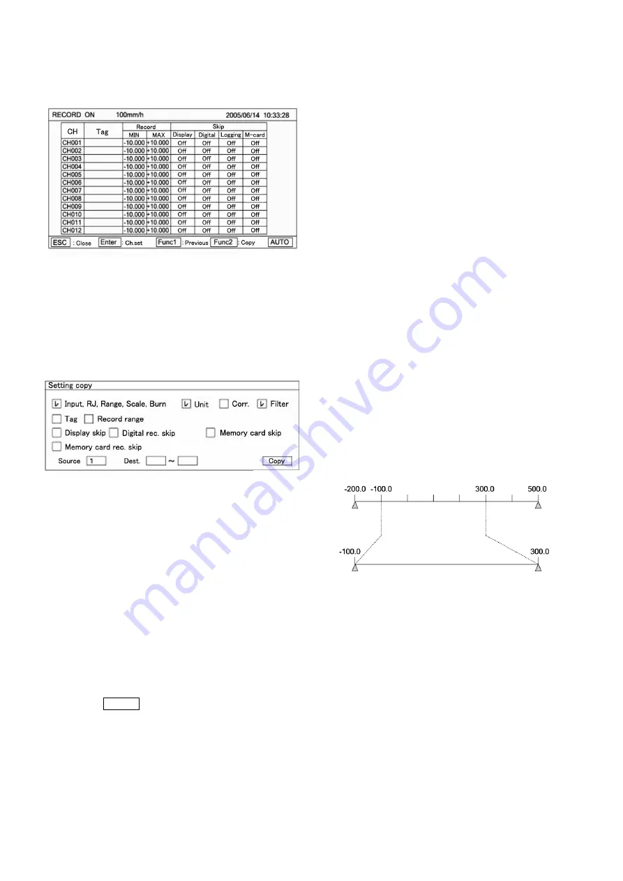
  By pressing Func1 in the screen display in 

 above, 

the following screen is displayed. Screens 


are used for confirming the setting and copying the 
setting items in the setting screen to the other 
channels.  


  For returning to screen 

 from screen 

, press 

Func1 key again.       

 Screen 

  can also be displayed by pressing Enter 

key after moving the cursor to a desired channel 
number to be set by 

 keys in this screen.   

  For copying channel parameters to the other 

channel, press Func2 key in either screen 

 or 

  Move the cursor to a desired item to be copied by 

 keys. 


Each time Enter key is pressed once, [

]/[  ] is 

repeated.  
Select [

] for a desired setting item to be copied, and 

select [    ] for a setting item to be not copied.   
Press Enter key after moving the cursor to the copy 
source.   
After inputting a desired channel number as the copy 
source by numeric keys, press Enter key, and the 
cursor moves to the copy destination. By pressing 
Enter key furthermore, the channel number at the 
copy destination can be input by numeric keys.     
By pressing Enter key after inputting a channel 
number at the copy destination, the cursor moves to 
[~]. Press Enter key, and the channel number at the 
copy destination can be input by numeric keys.       
After the end of setting on this screen, bring the 
cursor to    Copy   .  

  Terminate the copy by pressing Enter key.   


When the input kind, scale lower-limit, and scale 

higher-limit are changed in the setting of a channel 
parameter, other settings (set value, dead band etc.) 
may be influenced. 

Resolution of analog recording depend on setting 

value of scale lower-limit/higher-limit, not depend on 
setting of chart recording lower-limit/higher-limit.


[Points] Channel parameter setting short-cut   

Items 

-

  on the last page can be short cut so long as 

the channel parameter setting is concerned. Bring the 
cursor to a desired channel to be set by 


keys in each display mode of one-point display, 12-point 
collective display, or all-point collective display, and then, 
press Enter key.     
Screen 

  on the last page is displayed and the setting 

can be done by the same operation.   

1. In case of one-point display, no cursor is displayed, but 

the channel in which Enter key was pressed can be set. 

2. In 12-point collective display/all-point collective display, 

the cursor is present on a channel number. Move the 
cursor by pressing 

 keys. 

3. When the channel parameter setting short-cut was used, 

no copy function is provided on the setting screen.   

4.For setting [

], bring the cursor to the unit, and press 

the Enter key for enabling the parameter input. [Shift] is 
displayed below the setting screen (refer to page 8-4: 8. 
Switching of keys). Press the shift key and high-light [A], 
and press the key of right next shift key 4 times. Then, 
input C and press Enter key for termination setting unit.   

[Setting example]   

Setting relation of [Scale lower-limit], [Scale higher-limit], 
[Chart recording lower-limit] and [Chart recording higher- 
limit].  

 Use K (-200.0 to 500.0) for input.   

 Set [Scale lower-limit] to -200.0.   

 Set [Scale higher-limit] to 500.0.   

 Set [Chart recording lower-limit] to -100.0. 

 Set [Chart recording higher-limit] to 300.0.   

The recording range is reflected by each setting as 
shown in the following figure.   


(Caution 1)


Range lower-limit and higher-limit, scale higher-limit and 
lower-limit, and chart recording lower-limit and higher-limit 
can be set up to max. 5 digits (or can be set up to max. 6 
digits if minus [-] is included). 
If a numeric value includes a decimal point, however, the 
numeric value excluding the decimal point is limited up 
to ±30000. 
Example: Settable up to ±300.00 

If 500.00 is set, a message [The input value is 
abnormal] is displayed and the setting is not 
acceptable. Units and tags can be set up to max. 8 
digits.  

(Caution 2)


For moving between channels, use 

 keys.   

In the channel parameter setting mode, channels 1

12 

are displayed. For moving to channels 13

24, move the 

cursor to channel 12, and press 

 key.


For moving to 

channels 1

12 under the displayed condition of channels 

13

24, on the contrary, press 

 key. 


Scale lower-limit

Scale higher-limit

Chart recording 

lower-limit

Chart recording 

higher-limit

Scale span 

Scale zero

Recording zero

Recording span


Summary of Contents for LE5100

Page 1: ...INST No INE 364B I Instruction Manual LE5100 Hybrid Recorder LE5200 Operation Type Intelligent Recorder ...

Page 2: ......

Page 3: ...in any form 2 Alteration of the description contents in this manual is reserved without notice 3 For the contents of this manual we make assurance doubly sure However if a doubtful point an error and or a description failure should have found please inform your nearest branch or sales office 4 You are requested to understand that we are not responsible for any operation results Thank you for your ...

Page 4: ...nnections are correct the power voltage conforms to the specified voltage and also the protective grounding is done without fail before feeding the power supply Don t put your hand into the case Don t put your hand into the internal unit rack or case except for the positions where are necessary for operating the unit otherwise you may receive an electric shock or you may be injured Stop feeding th...

Page 5: ... 3 Mounting method 4 Connections 4 1 Cautions on connections 4 2 Terminal boards rear panel 4 3 Connections of each terminal board 4 3 1 Measuring input terminal board 4 3 2 Power terminals 4 3 3 Communication I F terminals contact output terminals and external drive terminals 4 3 4 Alarm output terminals 5 Installation of auxiliary products 5 1 Mounting method of chart 5 2 Ribbon cassette mountin...

Page 6: ...asuring data saving by PC card 8 17 7 Setting of set value saving by PC card 8 17 8 Setting of reading out a set value by PC card 8 17 9 PC card format 8 17 10 PC card removing 8 1 8 1 8 1 8 1 8 1 8 1 8 1 3 8 4 8 4 8 4 8 4 8 5 6 8 7 8 8 9 8 10 8 11 8 12 8 13 14 8 15 17 8 18 20 8 21 8 22 8 23 8 24 8 25 8 26 8 27 8 28 8 29 8 30 8 30 8 30 8 30 8 31 8 31 8 32 8 33 8 34 8 35 8 36 9 Adjustment function ...

Page 7: ...hannel 1 2 Profile This unit comprises a 12 point input type a 24 point input type and a 36 point input type This unit can be operated and set without opening the door in all types 1 3 Input types This unit is characterized with a full multi range of thermocouple TC resistance thermometer bulb and DC voltage mV V inputs 1 4 Check and confirmation Check the unit for the following items before opera...

Page 8: ...put Communications interface Contact 1 output option N None 1 Either RS 422A or RS 485 Ethernet Contact 1 output Contact 1output is a mechanical relay a contact output External drive option N Not provided 1 Provided Chart speed selection 3 speeds stop Data printing start Others option N None 1 Recording format change ratio differential alarm 2 Recording format change ratio differential alarm arith...

Page 9: ...onally every channel out of 10 colors Page 8 10 Tag number printing Tag numbers channel numbers are printed beside the trend recording at a fixed interval Scale and unit printing A scale and a unit are printed at both ends of the chart every fixed time Alarm mark printing When an alarm occurred or when the alarm was reset _ red or_ green mark is printed beside the trend recording and also the time...

Page 10: ...e engineering software option with a PC employed as the setting tool Setting contents can be confirmed 7 Self diagnostic function Self check function Instrument conditions are checked by executing self diagnosis at all times Setting decision function Setting contents are checked to inform of abnormal conditions if any 1 Defective contents check Format check Restriction check 2 A window is opened o...

Page 11: ... put strong force on the door frame 2 2 Front section of internal unit 2 3 Display status ALM Red LED flickers in the occurrence of an alarm PC CARD Green LED remains lit when PC card is being inserted REC ON Green LED lights when recording is turned on Recording is turned on or off by REC key CHINO CHINO brand lights when power is turned on Display Door grip Operation and setting keys Printer hea...

Page 12: ... 12 points are displayed collectively In case of the instruments where No of input points is 12 points Skipped channels are kept blank Each display area is not changed The same processing also applies to the channels where no range is set Measured values display is updated every second 5 Measuring data are fixed or sequentially displayed every 12 points In case of the units where No of input point...

Page 13: ...recording This key is used together with Enter key Data print key Prints data momentarily when pressing this key This key is used together with Enter key Feed key Feeds the chart at a speed of 750mm min when this key is being pressed Shift key Selects numeric keys and alphabetic or other symbolic keys Numeric key Used for inputting a numeric value Alphabetic key Used for inputting alphabetic chara...

Page 14: ...2000m Working place Indoors 3 2 Panel mounting method 3 2 1 External dimensions 3 2 2 Panel cutout Panel cutout and Minimum mounting dimensions 3 2 3 Mounting method Insert this unit into the panel cutout of the instrument panel Screw in four attached mounting screws into the screw holes at 2 upper and lower places 4 places in total on the right and left side panels of the unit Insert the mounted ...

Page 15: ...ucing a reference junction compensation error Avoid the solar radiation or the like 4 Separate the unit from a noise source Separate the unit from a noise source as far as possible otherwise an unexpected trouble may occur Take a noise preventive measure if the unit cannot be separated form a noise source Major generation sources An electromagnetic switch or the like A power line having waveform d...

Page 16: ... than 30VAC or 60VDC Make sure that noises are lower than specified After connecting terminals mount a terminal cover for preventing an electric shock accident and also protecting the input wires In case of the thermocouple input a reference junction compensation error is reduced by mounting the terminal cover 4 3 2 Power terminals Cautions 1 Turn off the feed power source without fail before conn...

Page 17: ...cable LE PC A LAN function is attached PC A LAN function is attached Hub Twisted paired straight cable STP straight cable LE Line converter SC8 10 PC side 9 pins connector RD SD SG RDA RDB SDA SDB 1 2 3 4 5 6 7 8 9 RDA RDB SDA SDB LE SG RD SD SG RDA RDB 1 2 3 4 5 6 7 8 9 RDA RDB SDA SDB Line converter SC8 10 LE For RS485 short SDA and RDA and also SDB and RDB respectively PC side 9 pins connector ...

Page 18: ... AC or 60V DC or use manual contacts 4 3 4 Alarm output terminals Caution 1 The alarm output is a mechanical relay a contact output For connections refer to 3 Connections of output relay terminals Cautions 1 Connect a load of less than the designated contact capacity to the output relay terminals 2 Turn off the feed power source and buffer relay power supply before starting connections for prevent...

Page 19: ... horizontally under the condition Shuffle the chart sufficiently before setting the chart for preventing a double feed Chart rack unit Fit the holes at both ends of the chart to the chart drum sprocket After setting the chart reset the front chart holder and chart folder to their original positions from being tilted down conditions in Pull down the front chart holder and chart holder before settin...

Page 20: ...op view shown below The ribbon cassette is mounted diagonally as illustrated below Make sure that face A of the printer carriage and face B of the ribbon cassette are mounted without any clearance When the ribbon cassette is mounted completely a click is heard by the locker spring Move the printer carriage to about the center by hand After the ribbon cassette has been mounted normally straighten t...

Page 21: ...12 point measuring data are collectively and sequentially displayed 24 point and 36 point units excluding 12 point unit 6 Type code serial number software version number of this unit are displayed Display update cycle Display update cycle of measuring data 1 second Display update cycle of input channels 2 seconds Setting of this factory delivery value can be changed Collective display update cycle...

Page 22: ...stopping the setting the screen returns to the last one each time Esc key is pressed once Terminate the setting by pressing Enter key By pressing Enter key the latest scan data at that time are digitally recorded Caution 1 Format is set by DATA PRINT of the menu Caution 2 If digital recording is necessary at a fixed interval use either data interval recording or logging recording Caution 3 Not emp...

Page 23: ...value of chart speed 28 8sec 9 Digital recording format Data interval Data I Logging recording Data printing Data P Not set Not set 1 line 6 channels printing 10 Analog recording format Format Standard Recording colors Channel numbers Recording colors 1 11 21 31 41 51 61 71 Green 2 12 22 32 42 52 62 72 Yellowish green 3 13 23 33 43 53 63 Orange 4 14 24 34 44 54 64 Red 5 15 25 35 45 55 65 Reddish p...

Page 24: ...is displayed 2 Detail setting When enter 332 display a screen like below so setup according to the following procedure When select 7 to 0 by key and then press enter key ON OFF are switched every pressing enter key After every selects are done cursor is moved to SET by key and press Enter key to terminate the setting 7 Time printing ON OFF 6 Scale printing ON OFF 5 Alarm activation reset printing ...

Page 25: ... setting parameters depends upon the setting items One parameter is provided for time and chart speed while several parameters requiring the designation of channels are provided for ranges scales and alarms 6 Confirmation of setting parameters Setting parameters can be set in two ways One is the list printing to confirm all setting items or designated setting items by printing them while the other...

Page 26: ...g parameters return to the last screen by pressing Esc key In case of the left procedure example the screen is reset to the start screen by pressing Esc key twice If setting change or addition is done after confirming various setting parameters use keys and numeric keys Press Enter key to terminate the setting change addition 1 Confirmation method in case of one setting parameter Start Menu key Se...

Page 27: ...ing the setting parameters of the channel to be confirmed press Esc key to return to the last screen and repeat steps Press Esc key if setting change addition is not done In case of the left procedure example the screen is reset to the start screen by pressing Esc key twice If setting change or addition is done after confirming various setting parameters use keys and numeric keys Press Enter key t...

Page 28: ...etting parameter has been high lighted as shown in the example Then input new parameter directly 8 Switching of keys When alphabetic keys or symbol keys are used switch them by pressing Shift key This switching can be done only when alphabetic or symbol keys are necessary for Units Tags Messages etc Example Setting of message printing 9 Setting change mark When a setting parameter is entered a set...

Page 29: ...hown in is displayed when selecting setting parameters as shown in this example Select a setting parameter by using keys in this window For setting the chart speed bring the cursor to meet the chart speed by keys and press Enter key 4 By pressing Enter key after setting the parameter input area optional cycle is high lighted By pressing Enter key under this condition parameter input area is high l...

Page 30: ...ameter input area has been set in the same way define is high lighted When no error occurs in setting parameters of all setting items press Enter key and the setting ends If a setting item is in error to move to the other setting item press keys and the move can be done to each setting item on condition that Enter key is not pressed yet Point 1 When the cursor is present on a setting item the sett...

Page 31: ...irmed Select 1CH 12CH or 36CH After selection the desired display mode to be set is defined Either fixed display or sequential display is selectable in each display mode AUTO Sequential CONST Fixed are switched from each other each time Func1 key is pressed once For stopping the setting the screen returns to the last one each time Esc key is pressed once A list of the kinds of display 1 1CH 1 poin...

Page 32: ...rection Unit Lower limit of chart recording Higher limit of chart recording Tag Display skip Digital printing skip Memory card recording skip Set each time Enter key is pressed once CH No is fixed to the channel number selected in the setting table display collective 12 points screen For the parameter input areas for input RJ burn filter and various skips setting parameters are selected Select the...

Page 33: ...Enter key Screen on the last page is displayed and the setting can be done by the same operation 1 In case of one point display no cursor is displayed but the channel in which Enter key was pressed can be set 2 In 12 point collective display all point collective display the cursor is present on a channel number Move the cursor by pressing keys 3 When the channel parameter setting short cut was use...

Page 34: ...ording position in units of every step Set the ZERO side of the chart to 0 and the SPAN side to 100 For this setting input them to the chart recording lower limit higher limit setting parameter input area by numeric keys The settable recording position range is 0 to 99 The higher limit is MAX 100 4 Unit tag and skip can be set in the same way as in normal input Input connection Note When the paral...

Page 35: ... memory card recording skip only The cursor moves to the other items but no setting can be done 3 Change the setting of recording range Lower limit 3000 0 higher limit 3000 0 are already set in setting parameter input area of chart recording lower limit higher limit Change the setting value include decimal point position depending on the communication input value 4 Unit tag and skip can be set in ...

Page 36: ...other keys for tags and input setting parameters to the parameter input area For other parameter input area select setting parameters A window opens to be ready for selection by keys After the end of setting in this screen bring the cursor to Set Terminate the setting change addition by pressing Enter key Press Esc key if the setting contents are not saved Caution 1 Default 001 002 are input displ...

Page 37: ...rameter to the chart speed parameter input area by using numeric keys For this setting set the chart speed to an optional value in units of 1mm h within a range of 1mm to1500mm h 2 The dotting synchronization parameter input area adopts the setting parameter selection system Open the window and select a setting parameter by keys For selecting the dotting synchronization refer to the following tabl...

Page 38: ...king dotting of chart speed Optional cycle In case of interlocking dotting at an optional cycle Caution 3 Dotting cycle The analog dotting cycle of this unit is basically set to dot once every 0 2mm in the time axis direction The chart speed interlocking value is calculated by the following formula Accordingly the latest data are dotted by setting the optional cycle to be shorter than the interloc...

Page 39: ...s printed black except for the occurrence and cancellation marks When the alarm occurrence or cancellation is printed a printing space is secured for avoiding overlapped printing so that the following printing is not done Caution 2 Max 120 occurred and cancelled alarms can be stored into memory Alarm occurrence and cancellation printing newly occurred during this period is not accumulated 2 No of ...

Page 40: ...ter selection system A windows opens to be ready for selection by using keys For output relay No set values and dead band input setting parameters by using numeric keys After setting has been terminated on this screen bring the cursor to Set Terminate the setting change addition by pressing Enter key Press Esc key if the setting contents are not saved Caution1 If an alarm output and contact output...

Page 41: ...Press Enter key and the channel number at the copy destination can be input by numeric keys After the end of setting on this screen bring the cursor to Copy Terminate the copy by pressing Enter key Point Each level when setting and copying an alarm includes the kind of alarm and a set value an alarm value being set to the level 5 Alarm check Whether an alarm occurred or not can be recognized in no...

Page 42: ...cording Set a unit as occasion demands For the analog recording range estimate a Difference value in advance before setting it Caution 1 Use CH No 37 72 as differential operation recording channels Caution 2 Carry out differential operation by neglecting the unit Caution 3 The analog recording range of the differential operation recording channel is set by setting channel parameters For setting th...

Page 43: ...p digital printing skip and memory card recording skip only The cursor can move to other items but setting cannot be done Select input setting parameters in and after CH037 from 2 kinds consisting of Not used and Operation Select Operation when a channel is used as an operation output channel Copy of channel parameters for operation output channel Set this item in the same way as in 8 3 Channel pa...

Page 44: ...ens to be ready for selection by using keys For other items input setting parameters by using numeric keys After setting has been terminated on this screen bring the cursor to Set Select the parameter input area for kind from the following items When SUB is selected setting of reference value C is invalid When SUI is selected setting of Y CH is invalid Terminate setting change addition by pressing...

Page 45: ...dow opens to display the setting parameter entry screen For the setting parameter entry screen refer to For stopping the setting the screen returns to the last once each time Esc key is pressed once Move the cursor to a desired item to be set by keys The cursor moves in the sequence of Input CH Message Printing each time Enter key is pressed once Input an optional channel number to the input CH pa...

Page 46: ...w opens to display the setting parameter entry screen For the setting parameter entry screen refer to For stopping the setting the screen returns to the last once each time Esc key is pressed once Move the cursor to a desired item to be set by keys The cursor moves to Printing item Printing each time Enter key is pressed once The parameter input area of printing items adopts the setting parameter ...

Page 47: ...rt time hours and start time minutes input setting parameters by numeric keys For selecting formats refer to the following table After the end of setting in this screen bring the cursor to Set Terminate the setting change addition by pressing Enter key Format None TAG DATA 1CH line TAG DATA UNIT 6CH line TAG DATA UNIT 10CH line For printing examples of formats refer to 8 12 Data print recording se...

Page 48: ...ut area adopts the setting parameter selection system A window opens to be ready for selection by keys For the recording interval hours recording interval minutes start time hours and start time minutes input setting parameters by numeric keys For selecting formats refer to the following table After the end of setting in this screen bring the cursor to Set Terminate the setting change addition by ...

Page 49: ...g table After the end of setting in this screen bring the cursor to Set Terminate the setting change addition by pressing Enter key Format TAG DATA UNIT 6CH line TAG DATA UNIT 10CH line A printing example by format Start Menu key Set Esc key NO End YES Setting change addition by using keys numeric keys etc Selection of setting items by keys Enter key Setting parameter display Enter key Setting end...

Page 50: ... item to be set Select DISPLAY Enter the parameter entry mode of a desired item to be set by pressing Enter key A window opens to display the setting parameter entry screen For the setting parameter entry screen refer to For stopping the setting the screen returns to the last once each time Esc key is pressed once The cursor moves to a desired item to be set by keys The cursor moves to Unit Tag CH...

Page 51: ...be set Select ENG Enter the parameter entry mode of a desired item to be set by pressing Enter key A window opens to display the setting parameter entry screen For the setting parameter entry screen refer to For stopping the setting the screen returns to the last once each time Esc key is pressed once The cursor moves to a desired item to be set by keys The cursor moves to USB identification addre...

Page 52: ...r entry mode of a desired item to be set by pressing Enter key A window opens to display the setting parameter entry screen For the setting parameter entry screen refer to For stopping the setting the screen returns to the last once each time Esc key is pressed once The cursor moves to a desired item to be set by keys The cursor moves to AD Month Day Hour Minute Second Set each time Enter key is p...

Page 53: ...m to be set by keys Press Enter key and input the 4 digit numeric value to the password input area Press Enter key to enable the setting change inhibition and permission Move the cursor to a desired item to be set by keys After the cursor has moved press Enter key and input レ to permit the setting After the end of setting in this screen bring the cursor to Set Terminate the setting change addition...

Page 54: ...ctly its residual quantity is indicated in the display section and the LED PC CARD lights green in the status section 8 17 3 Operation The operation comprises data writing DATA WR into the PC card set value saving PAR SAVE readout for a setting change PAR LOAD PC card formatting FORMAT and PC card removing REMOVE By inserting the PC card into the unit an error check is done automatically If an err...

Page 55: ...ce any dust into the connector when storing the product Don t touch the connector terminals nor make it contact with any metal otherwise its internal circuits may be broken due to static electricity 2 Cautions This CF card has been FAT formatted at the delivery time By using the PC card adapter the CF card can be used as a PC card conforming to PC Card Standard97 16 bit card specification All data...

Page 56: ...ence of Format Start TRG Start Hour Minute Relay No End TRG Rec time Hour Minute Interval pre TRG Set 1 For parameter input area of the Start Hour and relay No and Minute and Rec time Hour and Minute and parameter input area of pre TRG input setting parameters by numeric keys Select one output 800 to 836 for relay No Pretrigger is optional setting 0 to 100 by every 1 Pretrigger Example If pretrigg...

Page 57: ... to max 8digits by alphanumeric characters After the end of setting on this screen bring the cursor to save After the end of setting of the file name press Enter key Then file name is highlighted Use key and bring the cursor to save Terminate the setting change or addition by pressing Enter key If the set contents are not saved press Esc key Note 1 When a file name is entered on the setting parame...

Page 58: ...k For the setting parameter entry and check screen refer to Move the cursor to a desired item to be selected by keys Select Yes when reading out a set value or select No if not Start reading out the set value by pressing Enter key Select No or press Esc key if the save contents are not saved Note 1 When a set value is read out of the PC card the message display on the display screen turns blue Not...

Page 59: ...or No if not Start formatting by pressing Enter key Select No or press Esc key if formatting is not done Note 1 The PC card is formatted at the delivery time If the PC card has been formatted by a format other than FAT format formatting is necessary again For FAT formatting format the PC card by FAT16 or FAT32 by means of a personal computer FAT formatting cannot be done by this unit Note 2 When t...

Page 60: ...ng the screen returns to the last one each time Esc key is pressed once Move the cursor to a desired item to be selected by keys Select Yes if stop or No if not Stop operation by pressing Enter key Select No or press Esc key if not stop operation Note 1 It is a cause of trouble if the PC card is removed during operation When the PC card is removed always stop operation of the PC card first Start E...

Page 61: ...try mode of a desired item to be set by pressing Enter key A window opens to display the setting parameter entry screen For the setting parameter entry screen refer to For stopping the setting the screen returns to the last once each time Esc key is pressed once Select either zero side or span side by Func1 and Func2 keys Preset zero and span values are displayed on this screen These values change...

Page 62: ...r to For stopping the setting the screen returns to the last once each time Esc key is pressed once The cursor moves to a desired channel number to be set by keys The cursor does not shift to any item other than CH No Connect a tester to the channel to be set Select a channel to be set and press Enter key For the setting parameter entry screen refer to The value displayed on the zero side shows th...

Page 63: ... 2 Set a correction value by measured value zero span adjustment INPUT ADJ For details see 9 2 Display the setting entry screen in the left figure input 1 to a parameter input area and input a correction value to b parameter input area by numeric keys Bring the cursor to Set and terminate the entry by pressing Enter key Caution 1 If a correction value is set in channel parameter setting a correcti...

Page 64: ... 0 If an electronic reference junction temperature is used refer to its instruction manual for connections etc Be careful with the compensation accuracy Caution 3 If no reference junction temperature compensator RJ is available Adopt connection1 if RJ selection is set to Int in thermocouple input and no reference junction temperature compensator is available In this case set the RJ selector to Ext...

Page 65: ...ed smooth by Feed key See 24 5 None of Rec key Data P key and Feed key is acceptable Check the system setting See 8 16 Key Lock lights in the display section in key lock mode 6 Range is set but data are not displayed nor recorded as analog or digital data in a certain channel Check the dot setting See 8 4 7 Setting contents are confirmed to be different even after correct setting When setting is e...

Page 66: ...wer switch 3 Remove dirt from the printer main shaft by wiping it off with a soft cloth 4 Lubricate the main shaft with one or two drops of the attached lubricating oil Caution 1 If don t lubricate the main shaft for long time recording will be distorted Caution 2 Use the attached lubricating oil Don t use any other oil Caution 3 Don t lubricate any gears or other places If oil is attached to resi...

Page 67: ...e cycles Part names Reference exchange cycles Remarks Mechanical units or parts Printer 4 6 years Belt for driving the printer 4 6 years Chart drive device 4 8 years Ribbon cassette drive device 4 8 years Various motors 4 6 years Electrical units or parts Power supply unit 4 6 years At an ambient temperature of 25 Display unit 5 years At an ambient temperature of 25 Setting keys 4 6 years Relays M...

Page 68: ...B 50 60Hz 0 1 On condition that the noise peak value is less than the reference range Recording chart Folded belt type Total width 318mm Total length 20m Effective recording width 250mm No of recording points Input 12 points 24 points 36 points Arithmetic operation results 36 points Recording system Raster scan system 10 colors Wire dot printing Recording color Analog recording Optional designatio...

Page 69: ...nalog recording Alarm output 3 kinds of 12 points 24 points and 36 points AND output and OR output can be designated Contact capacity 100V AC 0 5A resistive load 240V AC 0 2A resistive load 30V DC 0 3A resistive load Power supply 100V AC 240V AC 50 60Hz Power consumption Approx 100VA Working temperature range 0 to 40 during transportation and storage 20 to 60 Working humidity range 20 to 80 RH dur...

Page 70: ...egory CAT Ⅱ Pollution degree 2 EMC directive EN61326 1 ClassA Indication value equivalent to 10 FS fluctuates during the test RoHS directive EN50581 When it is high humidity in that condition of transportation and storage readjustment will be needed For detail of readjustment refer to instruction manual 9 4 Calibration ...

Page 71: ...R 0 to 1760 20mV 0 05 1 S 0 to 1760 20mV B 0 to 1820 20mV N 0 to 600 20mV 0 1 0 1 0 to 1000 40mV 0 to 1300 80mV 0 1 1 W WRe26 0 to 2315 80mV WRe5 WRe 26 0 to 2315 80mV PtRh40 PtRh20 0 to 1888 20mV NiMo Ni 50 to 1310 80mV PlatinelⅡ 0 to 500 20mV 0 1 0 1 0 to 950 40mV 0 1 1 0 to 1395 80mV U 200 to 350 20mV 0 05 1 200 to 600 40mV L 200 to 350 20mV 200 to 700 40mV 200 to 900 80mV Resistance thermomete...

Page 72: ... C1606 1986 Exceptional standards of accuracy rating Note Each reference range conversion accuracy applies to thermocouple inputs Kinds of inputs Measuring ranges Accuracy rating K E J T L 200 to 0 0 2 1digit R S 0 to 400 B 0 to 400 Not specified 400 to 800 0 15 1digit U 200 to 0 0 3 1digit W WRe26 0 to 300 PtRh40 PtRh20 0 to 300 1 5 1digit 300 to 800 0 8 1digit NiMo Ni 50 to 100 0 2 1digit ...

Page 73: ...corded by switching the recording range Change ratio and differential alarms Change ratio alarm Alarm operation lifting limit lowering limit is done to a change width every fixed time of input Differential alarm Alarm operation differential higher limit differential lower limit is done to an absolute value of a difference of 2 inputs Caution Differential operation inter channel value fixed value f...

Page 74: ...e chart speed display changes but the unit is set to Rec OFF condition Note 3 If Stop is selected by an external contact the unit is set to Rec OFF condition irrespective of the keying operation and setting by means of communication If a set value is confirmed when Rec OFF is set by keying operation or communication under this condition a Rec ON condition returns but the unit is set to Rec OFF con...

Page 75: ...of the selection of chart speeds by an alarm output Description of operation in the above example The chart speed is 5mm H when no alarm occurs If a measured value becomes higher than 800 alarm output 1 turns on and the chart speed is switched to 50mm H If a measured value becomes higher than 1200 alarm output 2 turns on and the recording stops Alarm setting Necessary alarm point Higher limit 1000...

Page 76: ... set by keys Each time Enter key is pressed once the cursor moves in the sequence of EX1 EX2 EX3 EX4 chart speed 2 Dot sync 2 chart speed 3 Dot sync 3 Set 1 The EX parameter input area is determined by selecting a setting parameter A window opens Select the parameter by or key For selecting EX1 to EX4 refer to the following table 2 Input a setting parameter by using numeric keys in the chart speed...

Page 77: ...tting press Esc key The screen returns to the last one each time Esc key is pressed once Move the cursor to a desired item to be set by keys Each time Enter key is pressed once the cursor moves in the sequence of Relay No Set Input a setting parameter to the parameter input area at the output destination by pressing numeric keys Setting is as shown below Any setting other than described below cann...

Page 78: ...ect PRINT OPT Press Enter key to enter the parameter entry mode of the desired item to be set A window opens and a setting parameter entry screen is displayed For the setting parameter entry screen refer to For stopping the setting refer to Move the cursor to a desired item to be set by keys The format parameter input area is selected by selecting a setting parameter Bring the cursor to the format...

Page 79: ...the last one each time Esc key is pressed once Move the cursor to a desired channel number to be set by or key The cursor does not move to any item other than CH No After selecting a channel to be set press Enter key A window opens and a setting parameter entry screen is displayed For the setting parameter entry screen refer to Move the cursor to a desired channel number to be set by keys Each tim...

Page 80: ... to a desired channel number to be set by or key The cursor does not move to any item other than CH No After selecting a channel to be set press Enter key A window opens and a setting parameter entry screen is displayed For the setting parameter entry screen refer to Move the cursor to a desired channel number to be set by keys Each time Enter key is pressed once the cursor move in the sequence of...

Page 81: ...or key The cursor does not move to any item other than CH No After selecting a channel to be set press Enter key A window opens and a setting parameter entry screen is displayed For the setting parameter entry screen refer to Move the cursor to a desired channel number to be set by keys After pressing Enter key select No of areas by using or key After the end of setting in this screen bring the cu...

Page 82: ...d differential higher limit and differential lower limit Setting method 1 Refer to setting of alarm and set it Ⅰ Instruction manual 8 6 ALARM 2 Select U or D for kind 3 dt second is set optional time which is range 0 1 second to 1800 0 second by 0 1 second with using numeric keys 4 Refer to following figure for screen of setting list display collective 12 point 5 Refer to following figure for disp...

Page 83: ...ng of alarm and set it Ⅰ Instruction manual 8 6 ALARM 2 Select B or S for kind 3 Input channel for calculating input difference in differential Channel is 1 through 72 4 Refer to following figure for screen of setting list display collective 12 point 5 Refer to following figure for display of setting parameter recording Note 1 The cursor dose not move to parameter input area of unnecessary setting...

Page 84: ...ntial operation 1 Refer to setting of differential recording and set it Ⅰ Instruction manual 8 7 CALC 2 Select SUB or SUI for kind 3 Refer to following figure for screen of setting list display collective 12 point Unrelated items for type which is set in operation output channel is not display 4 Refer to following figure for display of setting parameter recording The cursor does not move to parame...

Page 85: ...ve 12 point Unrelated items for type which is set in operation output channel is not display 4 Refer to previous page 1 Differential operation for display of setting parameter recording The cursor dose not move to parameter input area of unnecessary setting depending on set operation type Select one from following for operation type of time series TMIN Minimum value every interval TMAX Maximum val...

Page 86: ... create operation formula Press Enter key when cursor is on the operation formula and create formula After end of creating operation formula bring the cursor to SET and press Enter key 4 1 Computation types 4 4 1 Mathematical calculation Four arithmetic operations are performed Symbol Example Remarks Totalizer X Y Subtraction X Y Multiplication X Y Division X Y Reminder X Y Exponential X Y X and Y...

Page 87: ...nt temperature DEW DEW T H Refer to 4 Dew point temperature X indicate the channel number When the channel data calculation is specified for executing with the settings of the designated channel number the calculated results of the designated channel number are used In addition when the designated channel number is greater than the channel number for calculation the calculation results obtained pr...

Page 88: ...lative humidity calculation B 0 000662 1013 0 D W A 100 Provision A Dry bulb saturated water vapor pressure B Wet bulb saturated water vapor pressure The following formula is used for the calculation of the saturated water vapor pressure 6 1121 EXP 17 502 T 240 9 T T Temperature 4 Dew point temperature Entering method of the formula DEW T H T Temperature data channel H Relative humidity channel Th...

Page 89: ......

Page 90: ...32 8 KUMANO CHO ITABASHI KU TOKYO 173 8632 Telephone 81 3 3956 2171 Facsimile 81 3 3956 0915 Printed in Japan ...

Reviews: