


72
Table 48 —
Fan Status Monitoring Configuration
Fan Stat Monitoring Type (SFS.M)
This configuration selects the type of fan status monitoring to
be performed.
0 - NONE — No switch or monitoring
1 - SWITCH — Use of the fan status switch
2 - SP RISE — Monitoring of the supply duct pressure.
Fan Fail Shuts Down Unit (SFS.S)
This configuration will allow whether the unit should shut
down on a supply fan status fail or simply alert the condition
and continue to run.
YES — Shut down the unit if supply fan status monitoring
fails, and send out an alarm.
NO — Do not shut down the unit if supply fan status monitor
-
ing fails, but send out an alert.
SUPPLY FAN STATUS MONITORING LOGIC
Regardless of whether the user is monitoring a discrete switch
or is monitoring static pressure, the timings for both techniques
are the same and rely upon the configuration of static pressure
control.
The configuration which determines static pressure control is
Configuration
SP
SP.CF
. If this configuration is set to
0 (none), a fan failure condition must wait 60 continuous sec
-
onds before taking action. If this configuration is 1 (VFD), a
fan failure condition must wait 3 continuous minutes before
taking action.
If the unit is configured to monitor a fan status switch (
SFS.M
= 1), and if the supply fan commanded state does not match the
supply fan status switch for 3 continuous minutes, then a fan
status failure has occurred.
If the unit is configured for supply duct pressure monitoring
(
SFS.M
= 2), then
• If the supply fan is requested ON and the static pressure
reading is not greater than 0.2 in. wg for the time clarified
above, a fan failure has occurred.
• If the supply fan is requested OFF and the static pressure
reading is not less than 0.2 in. wg for the time clarified
above, a fan failure has occurred.
Dirty Filter Switch
This unit is equipped with several filter stages. It is important
to maintain clean filters to reduce the energy consumption of
the system. This unit is designed to provide several ways to
achieve this goal. Table 49 shows the 9 configurations for filter
monitoring in this unit. If the configuration for either the main
or final filter is set to 0-Disable then the input is set to read
“Clean all the time.” There are several controls which need to
be used in conjunction with the filter configuration so that each
corresponding setting will operate correctly.
The fault status timer is a parameter that sets the number of
minutes the filter status must be in a fault state before the fault
latch is closed. To set the fault time, use
Configuration
FLTC
FS.FT
; the range is between 0 and 10 minutes. The
default for this parameter is 2 minutes.
Filter types (
MF_TY, PF_TY
) and final resistance (
MF_FR,
PF_FR
) are used for the Delta Pressure and Predictive Life
configurations for the main and post filter. The final resistance
will be automatically set when the filter type is selected. After
selecting a filter type, it is possible to change the filter final re
-
sistance. Settings for filters based on Tables 49 and 50 for main
and post filters.
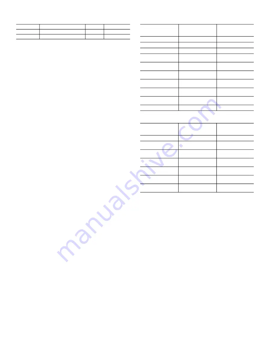
Table 49 —
Main Filter Types
Table 50 —
Post Filter Types
To change the filter type for the main filter, use
Configura
-
tion
FLTC
MF.TY
set between 0 and 9 according to the
main filter type table. To change the filter type for the post fil
-
ter, use
Configuration
FLTC
PF.TY
set between 0 and 6
according to the post filter type table. To adjust the final resis
-
tance for the main filter after a filter type has been selected, use
Configuration
FLTC
MF.FR
and set from 0 to 10. To ad
-
just the final resistance for the post filter, use
Configura
-
tion
FLTC
PF.FR
and set between 0 and 10.
1 = Switch
If the Filter configuration for either the main or post filter is set
to 1 (Switch), then a filter status switch should be installed.
The monitoring of the filters is based on a clean/dirty switch
input.
Monitoring of the main and post filter status switches is dis
-
abled in the Service Test mode and when the supply fan is not
commanded on. If the fan is on and the unit is not in a test
mode and either the main or post filter status switch reads
“dirty” for a user set continuous amount of time, an alert is
generated. Recovery from this alert is done through a clearing
of all alarms or after cleaning the filter and the switch reads
“clean” for 30 seconds.
2 = Schedule
Filter configuration for either main or post filter can be set to 2
(Schedule). In this mode the filter status is based on a schedule
set by the user. The status is determined by the amount of time
remaining in the filter life. The user sets the lifetime for the fil
-
ter in months from 1 to 60 (5 years). The default for this pa
-
rameter is 12 months. It is also possible to set a reminder and
reset the schedule.
ITEM
EXPANSION
RANGE
CCN POINT
SFS.S
Fan Fail Shuts Down Unit
No/Yes
SFS_SHUT
SFS.M
Fan Stat Monitoring Type
0 to 2
SFS_MON
MAIN FILTER TYPE
(MF_TY)
DESCRIPTION
MAIN FILTER FINAL
RESISTANCE
(MF_FR)
0
Std 2 in. MERV
1
1
4-in. MERV 8
1
2
4-in. MERV 14
1.5
3
12-in. MERV 14
Bag with 2 in. pre-filter
2
4
12-in. MERV 14
Bag with 4 in. pre-filter
2
5
19-in. MERV 15
Bag with 2 in.pre-filter
2
6
19-in. MERV 15
Bag with 4 in. pre-filter
2
7
12-in. MERV 14
Cart with 2 in. pre-filter
2.5
8
12-in. MERV 14
Cart with 4 in. pre-filter
2.5
9
Strion Air
2
POST FILTER TYPE
(PF_TY)
DESCRIPTION
POST FILTER FINAL
RESISTANCE
(PF_FR)
0
None
0
1
12-in. MERV 14 Cart
with 2 in. pre-filter
2.5
2
12-in. MERV 14 Cart
with 4 in. pre-filter
2.5
3
19-in. MERV 15
Bag with 2 in. pre-filter
2
4
19-in. MERV 15
Bag with 4 in. pre-filter
2
5
12-in. MERV 17
Bag with 2 in. pre-filter
3
6
12-in. MERV 17
Bag with 4 in. pre-filter
3
Summary of Contents for WeatherExpert 48N2
Page 135: ...135 Fig 18 48 50N Typical Power Schematic Nominal 075 Ton Unit Shown ...
Page 136: ...136 Fig 19 48 50N Typical Power Schematic Nominal Ton 90 150 Units Shown ...
Page 137: ...137 Fig 20 48 50N Main Base Board Input Output Connections ...
Page 138: ...138 Fig 21 48 50N RXB EXB CEM Input Output Connections a48 9307 ...
Page 139: ...139 Fig 22 48 50N EXV SCB Input Output Connections a48 9308 ...
Page 140: ...140 Fig 23 48N Typical Modulating Gas Heat Unit Control Wiring ...
Page 141: ...141 Fig 24 50N Typical Electric Heat Unit Control Wiring ...
Page 144: ...144 Fig 27 48N Typical Gas Heat Section Wiring Nominal Ton 120 to 150 Units ...
Page 145: ...145 Fig 28 48 50N Typical Power Component Control Wiring 460 v ...
Page 146: ...146 Fig 29 48 50N Component Control Wiring 575 v Nominal Ton 075 to 150 Units ...
Page 147: ...147 Fig 30 48 50N Component Arrangement Power Box ...
Page 148: ...148 Fig 31 48 50N Component Arrangement Control Box ...
Page 240: ...240 APPENDIX D VFD INFORMATION CONT Fig G VFD Bypass Wiring Diagram WHEN USED ...


