


96
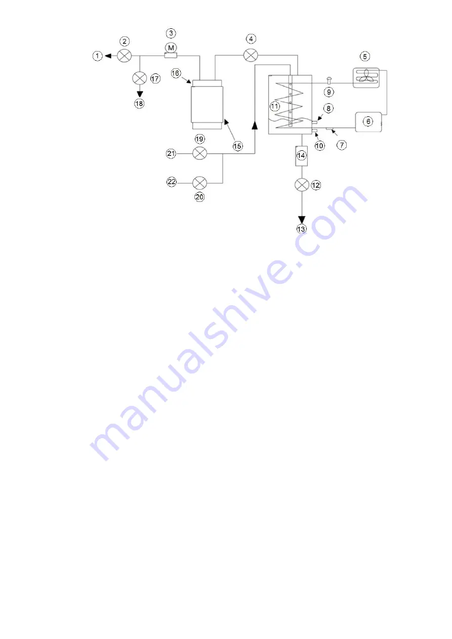
1 : Venting line
2 : Discharge valve
3 : Vacuum pump
4 : Pump out valve
5 : Condenser
6 : Compressor
7 : Suction temperature
8 : High level sensor
9 : Expansion valve
10 : Low level sensor
11 : Purge cooler
12 : Drain filter
13 : Chiller cooler
14 : drain filter
15 : Heater
16 : Carbon filter
17 : Regeneration valve
18 : Chiller cooler
19 : Compressor valve
20 : Condenser valve
21 : Chiller compressor
22 : Chiller condenser
Fig 53 - Purge operation sequence diagram
9.
MAINTENANCE
9.1 General maintenance
During the unit operating life the service checks and tests must be carried out in accordance with applicable
national regulations. If there are no similar criteria in local regulations, the information on checks during operation
in annex C of standard EN 378-2 can be used.
External visual checks: Annex A and B of standard EN 378-Corrosion checks: Annex D of standard EN 378-2.
These controls must be carried out:
• After an intervention that is likely to affect the resistance or a change in use or change of high-pressure
refrigerant, or after a shut down of more than two years. Components that do not comply, must be changed. Test
pressures above the respective component design pressure must not be applied (annex B and D).
• After repair or significant modifications or significant system or component extension (annex B)
• After re-installation at another site (annexes A, B and D)
Summary of Contents for PIC 5+
Page 26: ...26 VFD not shown Fig 13 Sensors actuators location ...
Page 52: ...52 Fig 24 19DV control box ...
Page 53: ...53 1 Power supply 24V AC 2 LEN 3 CCN 4 Ethernet 5 USB Fig 25 19DV HMI box rear view ...
Page 54: ...54 Fig 26 19DV IOB1 wiring Fig 27 19DV IOB2 wiring ...
Page 57: ...57 ...
Page 113: ...113 APPENDIX A SmartView SCREEN AND MENU STRUCTURE ...
Page 114: ...114 Detailed menu description ...
Page 116: ...116 APPENDIX B MAINTENANCE SUMMARY AND LOGSHEETS Cont 19DV monthly Maintenance Log ...


