49
NOTE: The dry contacts for the field inputs should be located as close to the unit as possible. The field wiring
should be capable of preventing electrical noise or induced voltage and should not be routed with any wires with
voltage over 50 v.
3.6.1 CONNECT CONTROL INPUTS
Wiring may be specified for a spare safety switch, and a remote start/stop contact can be wired to the terminal
strip. Additional spare sensors and control modules may be specified as well. Carrier Comfort Network® (CCN)
communication is wired to the machine HMI panel.
Wiring may be specified for a remote start/stop contact, a remote emergency stop contact, an ice build contact, a
spare safety switch, a power request feedback switch, a cooler water flow switch and a condenser water flow
switch can be wired to the control panel field terminal strip. Additional spare sensors may be specified for auto
demand limit input, refrigerant leak sensor, common CHWS temperature sensor, auto water temp reset and
common CHWR temp sensor can be wired to the control panel field terminal strips as well. These are wired to the
machine control panel. See electrical wiring diagrams.
3.6.2 CONNECT CONTROL OUTPUTS
Wiring maybe specified for a chiller alarm relay, a free cooling mode relay and a power request relay can be wired
to the control panel field terminal strip. Additional analog output signals may be specified for chiller running status
(on/off/ready) and head pressure output can be wired to the control panel field terminal strips as well. These are
wired to the machine control panel. See electrical wiring diagrams.
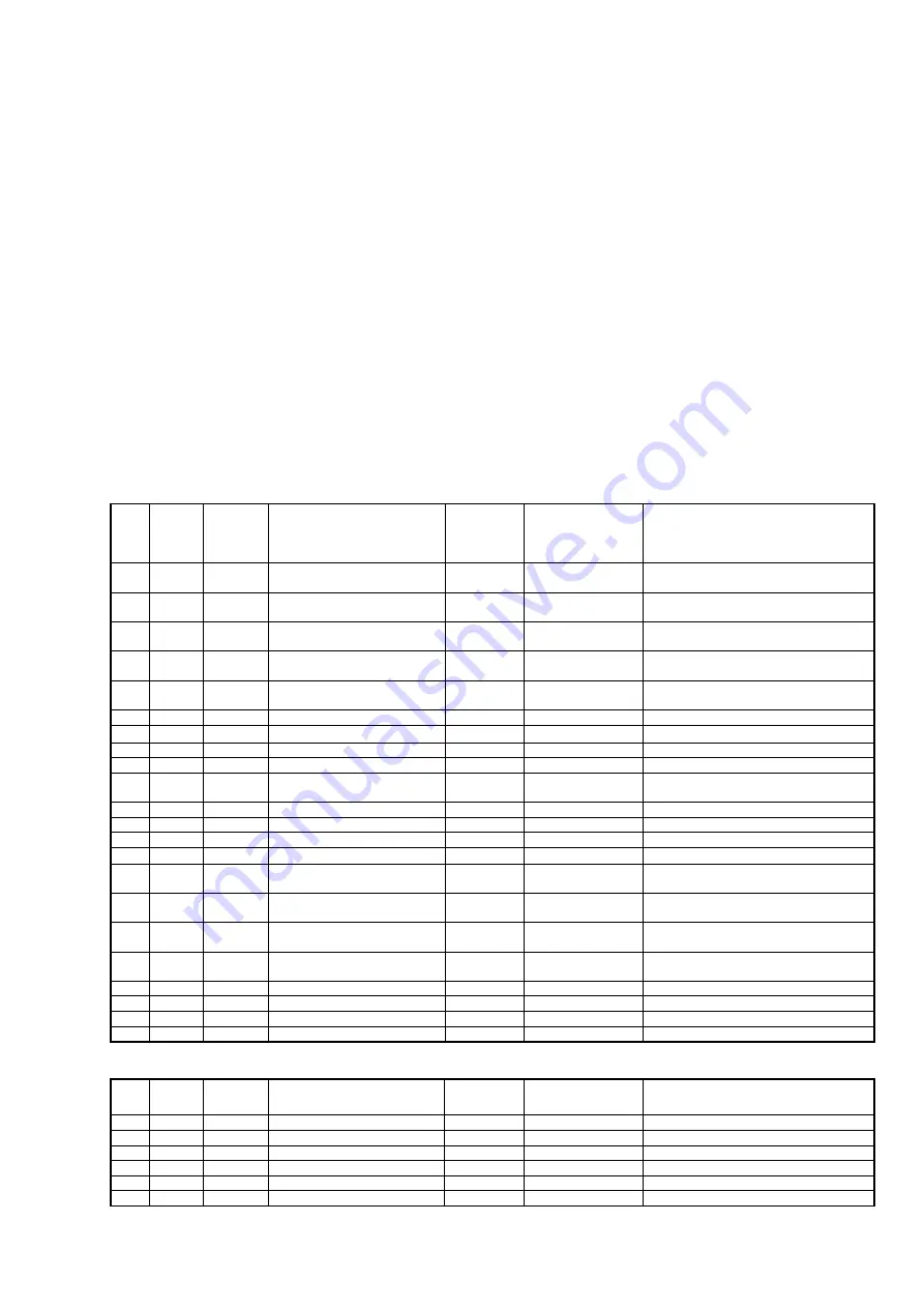
IOB1 BLOCK
Terminal
#
Point Description
Point name
Designation for
wiring diagram
Comments
AI1
J16
1-5
Entering chilled water
temperature
ECW
RT1
AI2
J16
2-6
Leaving chilled water
temperature
LCW
RT2
AI3
J16
3-7
Entering condenser water
temperature
ECDW
RT7
AI4
J16
4-8
Leaving condenser water
temperature
LCDW
RT8
AI5
J15
6-12
Evap. refrigerant liquid
temperature
EVAP_T
RT15
AI6
J15
5-11
Comp Discharge temperature
DGT
RT21
AI7
J15
4-10
Condenser pressure
COND_P
BP1
AI8
J15
3-9
Evaporator pressure
EVAP_P
BP3
AI9
J15
2-8
AI10
J15
1-7
FS VFD Load current
VFDC_MA
-
For freestanding VFD option - customer
terminals
AI11
J10
1-7
AO1
J14
1-4
Chiller Status Output mA
CHST_OUT
Chiller status
used in std
AO2
J14
2-5
AO3
J14
3-6
DI1
J13
1-5
Evap Water Flow Switch
EVAP_FS
-
User option, dry contact "Closed"
indicates "Flow" / not connected in std
DI2
J13
2-6
Cond Water Flow Switch
COND_FS
-
User option, dry contact "Closed"
indicates "Flow" / not connected in std
DI3
J13
3-7
Remote contact input
REM_CON
Remote on/off
User option, dry contact "Closed"
indicates Turn ON chiller
DI4
J13
4-8
Remote emergency stop input
E_STOP
Remote emergency
stop
User option, dry contact "Closed"
indicates Chiller Emergency stop
DO1
J12
6-7
Economizer bypass valve
ECBY_VLV
EBPV
Factory option
DO2
J12
9-10
Refrigerant Pump
REF_PUMP
KM1233
DO3
J12
1-2
Chiller Alarm Relay
ALM
K112
DO4
J12
4-5
Vapor Venting Line SV
VAPL_SV
-
not used / special
IOB2 BLOCK
Terminal
#
Point Description
Point name
Designation for
wiring diagram
Comments
AI1
J16
1-5
Motor winding temperature 1
MTRW1
RT31C
AI2
J16
2-6
AI3
J16
3-7
EC valve feedback Ma
HGBP_MA
Y11 13-14
factory option / 4 - 20 mA
AI4
J16
4-8
AI5
J15
6-12
Pump Outlet Pressure
PUMPO_P
BP81
AI6
J15
5-11
Bearing Outlet pressure
BRGO_P
BP71
Summary of Contents for PIC 5+
Page 26: ...26 VFD not shown Fig 13 Sensors actuators location ...
Page 52: ...52 Fig 24 19DV control box ...
Page 53: ...53 1 Power supply 24V AC 2 LEN 3 CCN 4 Ethernet 5 USB Fig 25 19DV HMI box rear view ...
Page 54: ...54 Fig 26 19DV IOB1 wiring Fig 27 19DV IOB2 wiring ...
Page 57: ...57 ...
Page 113: ...113 APPENDIX A SmartView SCREEN AND MENU STRUCTURE ...
Page 114: ...114 Detailed menu description ...
Page 116: ...116 APPENDIX B MAINTENANCE SUMMARY AND LOGSHEETS Cont 19DV monthly Maintenance Log ...