


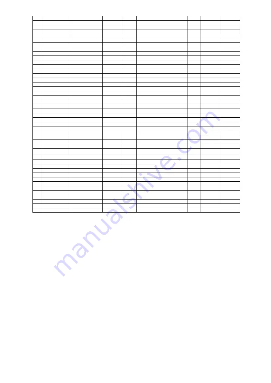
87
12
Q_GV1CL
0~1
0
Quick Test GV1 Close
0
1
X
13
Q_GVSRD
DISABLE/ENABLE
0
GV1/SRD Joint Test
0
1
X
14
Q_SRD
0.0~100.0
0
%
Quick Test Diffuser Pos
0
100
X
15
Q_GV1ACT
Guide Vane 1 Actual Pos
16
Q_DIFTGT
Diffuser Target Pos
17 Q_HGBPOP
0~1
0
Quick Test ECV Open
0
1
X
18
Q_HGBPCL
0~1
0
Quick Test ECV Close
0
1
X
19
Q_HGBP_T
0.0~100.0
%
EC Valve Tested Pos
0
100
X
20
Q_DMPOP
0~1
0
Quick Test Damper Open
0
1
X
21
Q_DMPCL
0~1
0
Quick Test Damper Close
0
1
X
22
Q_ALM
0~1
0
Quick Test Alarm Output
0
1
X
23
Q_ALE
0~1
0
Quick Test Alert Output
0
1
X
24
Q_CDWP
0~1
0
Quick Test Cond Pump
0
1
X
25 CDW_FLOW
NO/YES
0
Condenser Water Flow
0
1
26
Q_CHWP
0~1
0
Quick Test Chilled Pump
0
1
X
27 CHW_FLOW
NO/YES
0
Chilled Water Flow
0
1
28
CDW_DT
-40.0~245.0
0
° C
Condenser Water Delta T
-40
245
29
CHW_DT
-40.0~245.0
0
° C
Chilled Water Delta T
-40
245
30
Q_LLCEXV
0.0~100.0
0
%
Quick Test LLC EXV
0
100
X
31
Q_VFDCOL
0~1
0
Quick Test VFD Cooling
0
1
X
32
Q_VAPLSV
0~1
0
QCK TST Vapor Venting SV
0
1
X
33
Q_VSSV
0~1
0
Quick Test Vapor SV
0
1
X
34 Q_CONDSV
0~1
0
Quick Test Condenser CV
0
1
X
35
Q_EVAPSV
0~1
0
Quick Test Evaporator CV
0
1
X
36
Q_OPRLUB
0~1
0
QCK TST EvapDrain CV
0
1
X
37
Q_PRELUB
0~1
0
QCK TST Cond Drain CV
0
1
X
38
Q_CDPSV
0~1
0
Quick Test Purge Cond SV
0
1
X
39
Q_CMPSV
0~1
0
Quick Test Purge Comp SV
0
1
X
40
Q_POPSV
0~1
0
Quick Test Pumpout SV
0
1
X
41
Q_DRPSV
0~1
0
Quick Test Drainage SV
0
1
X
42
Q_RGPSV
0~1
0
Quick Test Rege SV
0
1
X
43
Q_DCPSV
0~1
0
Quick Test Discharge SV
0
1
X
44
Q_PVPSV
0~1
0
Quick Test Vacuum Pump
0
1
X
45
Q_PCPSV
0~1
0
Quick Test Purge Comp
0
1
X
46
Q_PHPSV
0~1
0
Quick Test Purge Heater
0
1
X
47
Q_MRC
0~1
0
Motor Rotation Check
0
1
X
48
Q_MRC_ST
Check State
IDLE=0, PreLub=1
Rotat=2, PosLub=3, End=4
49
Q_ECBP
0~1
0
Quick Test Eco Bypass
0
1
X
50
Q_ECONIV
0~1
QCK TST Eco Isolation
0
1
X
51 Q_CONDCV
0~1
QCK TST Cond Filling VLV
0
1
X
52 Q_LOWFAN
0~1
0
Quick Test Lo Tower Fan
0
1
X
53
Q_HIFAN
0~1
0
Quick Test Hi Tower Fan
0
1
X
Table 20 - PIC 5
– QUICK TEST LIST
5.9.1 Cooler and condenser pressure transducer and waterside flow device calibration
(Waterside Device Optional with IOB Inputs Available)
— Calibration can be checked by comparing the pressure
readings from the transducer to an accurate refrigeration gage reading. The transducer can be checked and
calibrated at 2 pressure points.
These calibration points are 0 psig (0 kPa) and between 10 psig (68.9 kPa) - 30 psig (206.8 kPa). To calibrate
these transducers:
1. Shut down the compressor and the cooler and condenser pumps.
NOTE: There should be no flow through the heat exchangers.
2. Disconnect the transducer in question from its Schrader fitting for cooler or condenser transducer calibration.
For pump pressure or bearing pressure or flow device calibration keep transducer in place.
NOTE: If the cooler or condenser vessels are at 0 psig (0 kPa) atmospheric pressure, the transducers can be
calibrated for zero without removing the transducer from the vessel.
3. Access the PRESSURE screen from the Main Menu and view the particular transducer reading (the cooler
pressure, condenser pressure, economizer pressure, pump inlet pressure, pump outlet pressure, bearing inlet
pressure, bearing outlet pressure). To calibrate a device, view the particular reading on the screen. It should read
0 kPa). If the reading is not 0 kPa, but within 35 kPa, the value may be set to zero while the appropriate
transducer parameter is highlighted. The value will now go to zero. No high end calibration is necessary for REF
PUMP DELTA P or flow devices. If the transducer value is not within the calibration range, the transducer will
return to the original reading. If the pressure is within the allowed range (noted above), check the voltage ratio of
the transducer. To obtain the voltage ratio, divide the voltage (dc) input from the transducer by the supply voltage
signal (See Maintenance Others in Maintenance Menu) or measure across the positive (+ red) and negative (
–
black) leads of the transducer. The voltage ratio must be between 0.80 and 0.11 for the software to allow
calibration. Rotate the waterside flow pressure device from the inlet nozzle to the outlet nozzle and repeat this
Summary of Contents for PIC 5+
Page 26: ...26 VFD not shown Fig 13 Sensors actuators location ...
Page 52: ...52 Fig 24 19DV control box ...
Page 53: ...53 1 Power supply 24V AC 2 LEN 3 CCN 4 Ethernet 5 USB Fig 25 19DV HMI box rear view ...
Page 54: ...54 Fig 26 19DV IOB1 wiring Fig 27 19DV IOB2 wiring ...
Page 57: ...57 ...
Page 113: ...113 APPENDIX A SmartView SCREEN AND MENU STRUCTURE ...
Page 114: ...114 Detailed menu description ...
Page 116: ...116 APPENDIX B MAINTENANCE SUMMARY AND LOGSHEETS Cont 19DV monthly Maintenance Log ...


