Axxius 800 - Release 2.2
3-11
Electrical Installation and Cabling
Chassis Connections
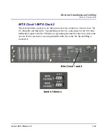
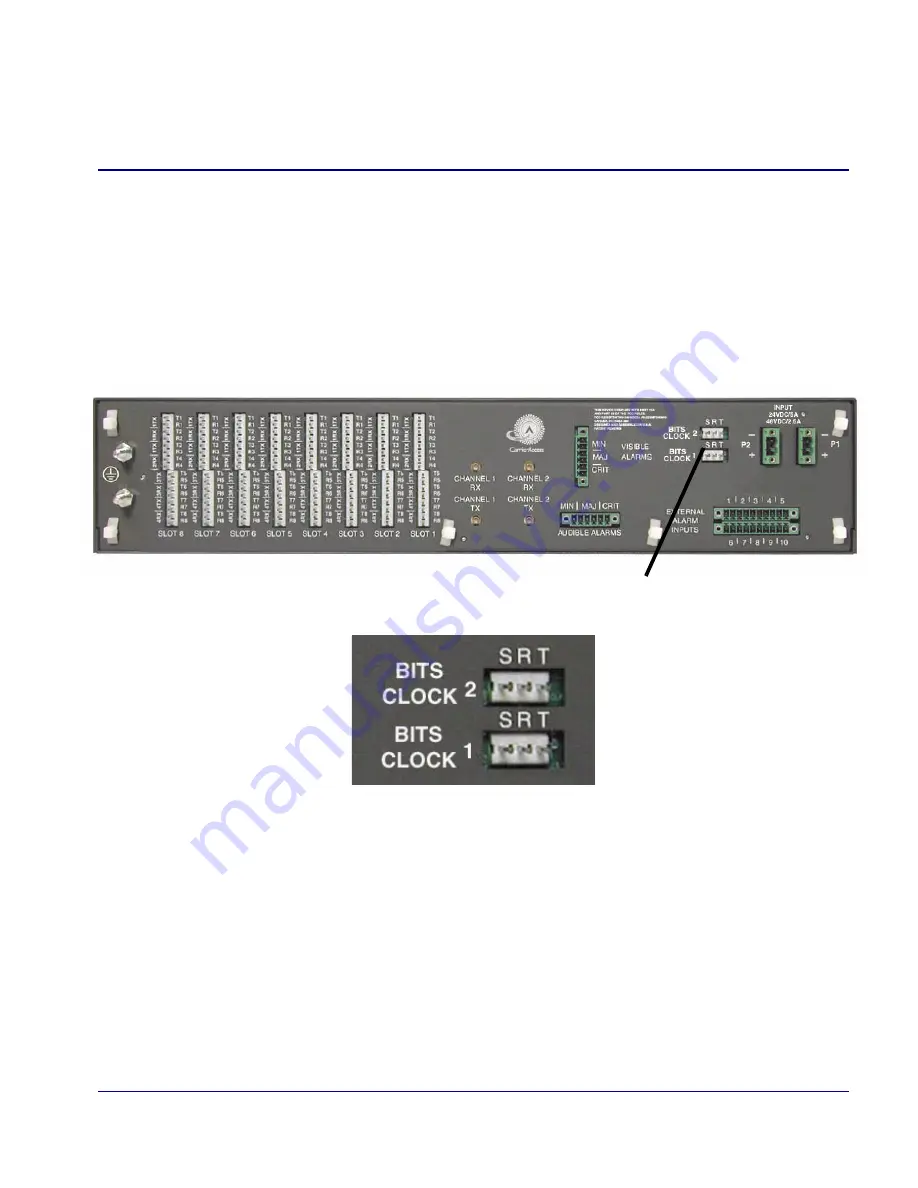
BITS Clock 1/BITS Clock 2
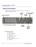
The external alarm connectors are three-pin wire-wrap connectors. One for each, Tip
(T), Ring (R) and Shield (S). Tip and Ring are the two connections for the 100 ohm
differential signal to the box. Shield is for grounding the shield of the clock cable to the
Axxius. If the customer is not using shielded cable, then only the Tip and Ring is
connected.
Bits Clock 1 and 2
back of Axxius
Summary of Contents for Network Device Axxius 800
Page 1: ...Axxius 800 USER MANUAL Part Number 770 0104 AG Product Release 2 2 May 2004 ...
Page 32: ...xxxii Axxius 800 Release 2 2 Table of Contents ...
Page 50: ...1 18 Axxius 800 Release 2 2 Base Platform ACO ...
Page 101: ...CHAPTER CLI Commands In this Chapter n Command Line Interface Help n CLI Commands ...
Page 392: ...8 8 Axxius 800 Release 2 2 FXO Voice Card Channel Associated Signaling CAS Conversions ...
Page 430: ...12 8 Axxius 800 Release 2 2 Power Supply Installing Replacing a Power Supply ...
Page 472: ...15 20 Axxius 800 Release 2 2 Terminal Server Router Card LEDs ...
Page 500: ...18 12 Axxius 800 Release 2 2 Maintenance Hot Swap Service Card ...
Page 532: ...C 22 Axxius 800 Release 2 2 Loopback Tests V 35 V 54 Loop ...
Page 552: ...Glossary 20 Axxius 800 Release 2 2 Glossary ...

