ZR70 MC A, ZR65 MC A, ZR60 A
CHAPTER 1. GENERAL DESCRIPTION OF PRODUCT
1-22
6-10 Direct print (ZR70 MC A, ZR65 MC A only)
After connecting the camcorder to the BJ 535PD or BJ 895PD camera direct printer using the
DIF-100 direct interface cable supplied with the printer, the user can easily print out still images
stored on a memory card. Compatible with DPOF printer settings (image and number of copies).
6-10-1 Printable images
On the ZR70 MC A, ZR65 MC A, still image files stored on an SD memory card or
MultiMediaCard only.
6-10-2 Print format
Single-image printing. Printing of index sheets is not supported. Supported paper sizes are L,
LL, postcard, A4, and card. Refer to the specifications of the BJ 535PD or BJ 895 PD printer for
information on compatible paper sizes.
6-10-3 Trimming
Not supported.
6-10-4 Date stamp
Not supported.
6-10-5 Number of copies printed
Can be specified between 1 and 99.
6-11 Other functions
6-11-1 Consecutive shooting mechanism
Can be used starting in Recording Pause or Stop mode, or starting with the power off. This does
not apply to cases where the cassette has been removed.
6-11-2 Automatic stop function
This function is activated in the following cases:
· When forward still image playback is continued for approx. 5 minutes, or reverse still image
playback is continued for approx. 5minutes
· When a condensation warning is displayed
· When the tape end or beginning is reached
6-11-3 Automatic power-off mechanism
Camera tape mode
After recording has been paused continuously for approximately 5 minutes. When the battery
voltage drops below the specified value.
Camera card mode
After a period of approximately 5 minutes elapses with the card inserted. When the battery
voltage drops below the specified value.
6-11-4 Time code
Automatically written during recording. Time code values range from 0:00:00:00 to 7:59:59:29
(hours:minutes:seconds:frames).
6-11-5 Photo search
This function searches for images shot in Photo mode.
Forward/reverse photo search (use the
,
keys on the remote control after selecting Photo
Search with the remote control Search Select key)
Values can be entered in a range of up to the
±
10
th
photo from the current position.
6-11-6 Date search
If there is more than one recording date, this function cue up to the position where the date
changes.
Forward/reverse date search (use the
,
keys on the remote control after selecting Date
Search with the remote control Search Select key)
Values can be entered in a range of up to the
±
10
th
photo from the current position.
6-11-7 World clock display
After setting a reference city (the city where the clock's time is set), when you take a picture,
select the name of the city where you are shooting. The date and time will be automatically
changed to the local date and time, and recorded in the data code.
6-11-8 Speaker
Built-in speaker. with volume adjustment
6-11-9 File transfer (ZR70 MC A, ZR65 MC A only)
When the USB port on the PC and the USB port on the camcorder are connected using the
included interface cable (IFC-300PCU), still images (JPEG files) and motion video (Motion
JPEG files) recorded on the memory card can be transferred to the PC.
If the "ZoomBrowser" program (for Windows) or "ImageBrowser" program (for Macintosh) on
the included Digital Video Solution Disk is installed on the PC in advance, you can transfer the
desired images to the PC while viewing thumbnails of the still images recorded on the memory
card.
6-11-10 A/D conversion
This function performs real-time conversion of analog AV signals input to the AV terminal into
digital DV signals and outputs them through the DV terminal.
When an 8 mm video player or VHS video player is connected with the camcorder using an AV
cable, and the camcorder is connected to a PC using a DV cable, playback images can be trans-
ferred from the 8 mm tape or VHS tape to the PC. (Under the VCR settings on the VCR menu
screen, set "AV input
→
DV Output" to ON.
Summary of Contents for ZR70 MC A
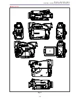
Page 12: ...ZR70 MC A ZR65 MC A ZR60 A CHAPTER 1 GENERAL DESCRIPTION OF PRODUCT 1 9 External View Fig 1 1 ...
Page 190: ...5 4 ZR70 MC A ZR65 MC A ZR60 A Front Cover Unit Section 4 1 2 6 7 8 3 2 5 3 3 ...
Page 194: ...5 8 ZR70 MC A ZR65 MC A ZR60 A Left Cover Unit Section 2 7 3 2 2 2 2 8 2 5 7 6 9 1 3 4 A A ...
Page 200: ...5 14 ZR70 MC A ZR65 MC A ZR60 A LCD Unit Section 1 3 2 1 3 4 5 10 2 6 7 9 8 ...
Page 202: ...5 16 ZR70 MC A ZR65 MC A ZR60 A Rear Cover Unit Section 7 4 1 1 3 5 8 6 8 4 2 CVF Unit 1 3 ...
Page 210: ...5 24 ZR70 MC A ZR65 MC A ZR60 A Lens Unit Section 3 2 10 4 5 7 9 8 7 8 1 3 6 2 6 2 ...
Page 212: ...5 26 DMC III Mechanical Chassis Section 1 1 3 9 5 7 8 6 4 2 3 3 ...
Page 214: ...5 28 DMC III Mechanical Chassis Section 2 1 2 3 4 5 6 7 8 6 1 9 10 13 11 12 ...
Page 216: ...5 30 DMC III Mechanical Chassis Section 3 2 2 2 2 2 3 3 8 9 2 10 11 12 13 4 6 7 5 1 ...
Page 218: ...5 32 DMC III Mechanical Chassis Section 4 1 3 4 5 8 9 6 10 7 2 ...

