ZR70 MC A, ZR65 MC A, ZR60 A
CHAPTER 4. DISASSEMBLING ADJUSTMENT
4-19
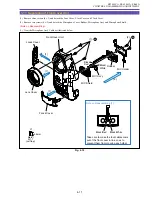
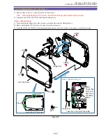
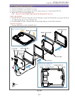
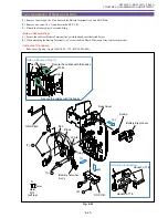
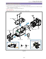
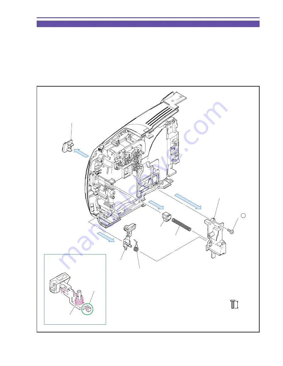
1-19 Disassembling of Right Cover Unit - 4
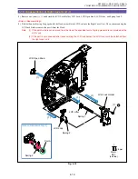
(1) Remove one screw (j
×
1) and detach the LCD Lock Holder, LCD Lock, LCD Open Knob, LCD Lifter, and Spring 1and 2.
<Note on Reassembling>
(1) With both ends of spring 2 engaged with the Hook, assemble the LCD Lock into the Right Cover Unit. Then, after mounting the
LCD Lock Holder, remove the part A from the Hook.
Note : (1) If the part-A side is not removed from the Hook, the specified level of spring pressure is not provided at the
LCD Lock.
(2) If the part is not unhooked after reassembling the LCD lock holder, the LCD lock could be detached from
the right cover unit.
Fig. 4-18
Note on Reassembling (1)
LCD Lock Holder
Spring 1
LCD Lifter
LCD Lock
Spring 2
Spring 2
Part A
LCD Open Knob
(1)
(1)
(1)
(1)
(1) - j
5.5mm
Metal
M1.7
(self tap)
j
Summary of Contents for ZR70 MC A
Page 12: ...ZR70 MC A ZR65 MC A ZR60 A CHAPTER 1 GENERAL DESCRIPTION OF PRODUCT 1 9 External View Fig 1 1 ...
Page 190: ...5 4 ZR70 MC A ZR65 MC A ZR60 A Front Cover Unit Section 4 1 2 6 7 8 3 2 5 3 3 ...
Page 194: ...5 8 ZR70 MC A ZR65 MC A ZR60 A Left Cover Unit Section 2 7 3 2 2 2 2 8 2 5 7 6 9 1 3 4 A A ...
Page 200: ...5 14 ZR70 MC A ZR65 MC A ZR60 A LCD Unit Section 1 3 2 1 3 4 5 10 2 6 7 9 8 ...
Page 202: ...5 16 ZR70 MC A ZR65 MC A ZR60 A Rear Cover Unit Section 7 4 1 1 3 5 8 6 8 4 2 CVF Unit 1 3 ...
Page 210: ...5 24 ZR70 MC A ZR65 MC A ZR60 A Lens Unit Section 3 2 10 4 5 7 9 8 7 8 1 3 6 2 6 2 ...
Page 212: ...5 26 DMC III Mechanical Chassis Section 1 1 3 9 5 7 8 6 4 2 3 3 ...
Page 214: ...5 28 DMC III Mechanical Chassis Section 2 1 2 3 4 5 6 7 8 6 1 9 10 13 11 12 ...
Page 216: ...5 30 DMC III Mechanical Chassis Section 3 2 2 2 2 2 3 3 8 9 2 10 11 12 13 4 6 7 5 1 ...
Page 218: ...5 32 DMC III Mechanical Chassis Section 4 1 3 4 5 8 9 6 10 7 2 ...


