ZR70 MC A, ZR65 MC A, ZR60 A
CHAPTER 3. INFORMATION FOR REPAIR · SERVICE HINTS
3-2
2. Setting
(1) Adjustments other than DMC-III : Perform adjustments in the product state.
(2) Tracking adjustment (DMC-III) and Envelope check : Perform them with the Setting A.
(3) Adjustments related to DMC-III other than Tracking adjustment, tape path system check and tape path system cleaning : Perform
them with the Setting B.
2-1 Setting A
Envelope Check)
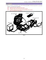
(1) Detach the Lithium Battery Cover.
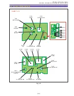
(2) Connect the extension connector (DY9-1387-000) to
CN2900.
(3) Observe the PB-RF waveform output from the extension con-
nector
Tracking Adjustment)
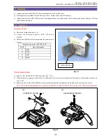
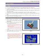
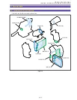
(1) Remove the CASSETTE COVER referring to Fig. 3-2 (a).
(2) When the posts are going to be adjusted, eject and remove the cassette once and perform the prospective adjustment as shown in
Fig. 3-2 (b).
(3) Repeat the observation of the PB-RF waveform and the prospective adjustment until fluctuation of envelope is re-moved.
Note : When the tracking adjustment is going to be performed, refer to Chapter 2-8 on page 4-48 : Tape Path Adjustment.
Pin No.
Signal Designation
7
GND
19
SWP
21
GND
23
PBRF
Extension connector (DY9-1387-000)
Fig. 3-1
DY9-1387-000
Fig. 3-2
(a)
(b)
×
2
×
2
CASSETTE COVER
ADJUSTMENT DRIVER
Summary of Contents for ZR70 MC A
Page 12: ...ZR70 MC A ZR65 MC A ZR60 A CHAPTER 1 GENERAL DESCRIPTION OF PRODUCT 1 9 External View Fig 1 1 ...
Page 190: ...5 4 ZR70 MC A ZR65 MC A ZR60 A Front Cover Unit Section 4 1 2 6 7 8 3 2 5 3 3 ...
Page 194: ...5 8 ZR70 MC A ZR65 MC A ZR60 A Left Cover Unit Section 2 7 3 2 2 2 2 8 2 5 7 6 9 1 3 4 A A ...
Page 200: ...5 14 ZR70 MC A ZR65 MC A ZR60 A LCD Unit Section 1 3 2 1 3 4 5 10 2 6 7 9 8 ...
Page 202: ...5 16 ZR70 MC A ZR65 MC A ZR60 A Rear Cover Unit Section 7 4 1 1 3 5 8 6 8 4 2 CVF Unit 1 3 ...
Page 210: ...5 24 ZR70 MC A ZR65 MC A ZR60 A Lens Unit Section 3 2 10 4 5 7 9 8 7 8 1 3 6 2 6 2 ...
Page 212: ...5 26 DMC III Mechanical Chassis Section 1 1 3 9 5 7 8 6 4 2 3 3 ...
Page 214: ...5 28 DMC III Mechanical Chassis Section 2 1 2 3 4 5 6 7 8 6 1 9 10 13 11 12 ...
Page 216: ...5 30 DMC III Mechanical Chassis Section 3 2 2 2 2 2 3 3 8 9 2 10 11 12 13 4 6 7 5 1 ...
Page 218: ...5 32 DMC III Mechanical Chassis Section 4 1 3 4 5 8 9 6 10 7 2 ...

