ZR70 MC A, ZR65 MC A, ZR60 A
CHAPTER 4. DISASSEMBLING ADJUSTMENT
4-26
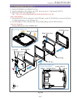
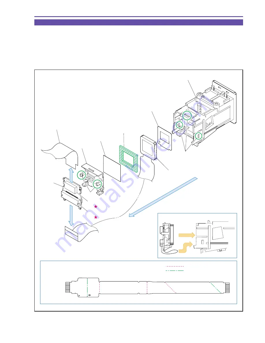
1-26 Disassembling of CVF Unit - 3
(1) Disconnect the CN4101 and detach the CVF-CAC FPC.
(2) Detach the three claw parts A and detach the components from the CVF P.C.B. to the Mask Plate.
(3) Detach the two claw parts B, disconnect the CN4102 and separate the CVF P.C.B., reflector and LCD Ass'y.
<Note on Reassembling>
(1) Treat the LCD Ass'y flexible cable by inserting it into the CVF Inner Cover as illustrated below.
(2) Before using the CVF-CAC FPC supplied for repair service, securely fold it at the position illustrated below.
Fig. 4-25
Note on Reassembling (1)
Note on Reassembling (2)
CVF-CAC FPC
TO
CN4101
DH2-5022-000
mk OR 1 03
CVF Inner Cover
Claw A
Claw B
Mask Plate
LCD Ass'y
Cushion
Diffuser
Reflector
CVF-CAC FPC
CVF
P.C.B.
(3)
CN4102
CN4101
(1)
(2)
Folding in a crest form
Folding in a trough form
Summary of Contents for ZR70 MC A
Page 12: ...ZR70 MC A ZR65 MC A ZR60 A CHAPTER 1 GENERAL DESCRIPTION OF PRODUCT 1 9 External View Fig 1 1 ...
Page 190: ...5 4 ZR70 MC A ZR65 MC A ZR60 A Front Cover Unit Section 4 1 2 6 7 8 3 2 5 3 3 ...
Page 194: ...5 8 ZR70 MC A ZR65 MC A ZR60 A Left Cover Unit Section 2 7 3 2 2 2 2 8 2 5 7 6 9 1 3 4 A A ...
Page 200: ...5 14 ZR70 MC A ZR65 MC A ZR60 A LCD Unit Section 1 3 2 1 3 4 5 10 2 6 7 9 8 ...
Page 202: ...5 16 ZR70 MC A ZR65 MC A ZR60 A Rear Cover Unit Section 7 4 1 1 3 5 8 6 8 4 2 CVF Unit 1 3 ...
Page 210: ...5 24 ZR70 MC A ZR65 MC A ZR60 A Lens Unit Section 3 2 10 4 5 7 9 8 7 8 1 3 6 2 6 2 ...
Page 212: ...5 26 DMC III Mechanical Chassis Section 1 1 3 9 5 7 8 6 4 2 3 3 ...
Page 214: ...5 28 DMC III Mechanical Chassis Section 2 1 2 3 4 5 6 7 8 6 1 9 10 13 11 12 ...
Page 216: ...5 30 DMC III Mechanical Chassis Section 3 2 2 2 2 2 3 3 8 9 2 10 11 12 13 4 6 7 5 1 ...
Page 218: ...5 32 DMC III Mechanical Chassis Section 4 1 3 4 5 8 9 6 10 7 2 ...

