ZR70 MC A, ZR65 MC A, ZR60 A
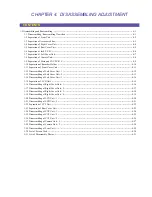
CHAPTER 4. DISASSEMBLING ADJUSTMENT
4-4
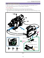
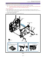
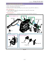
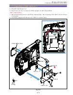
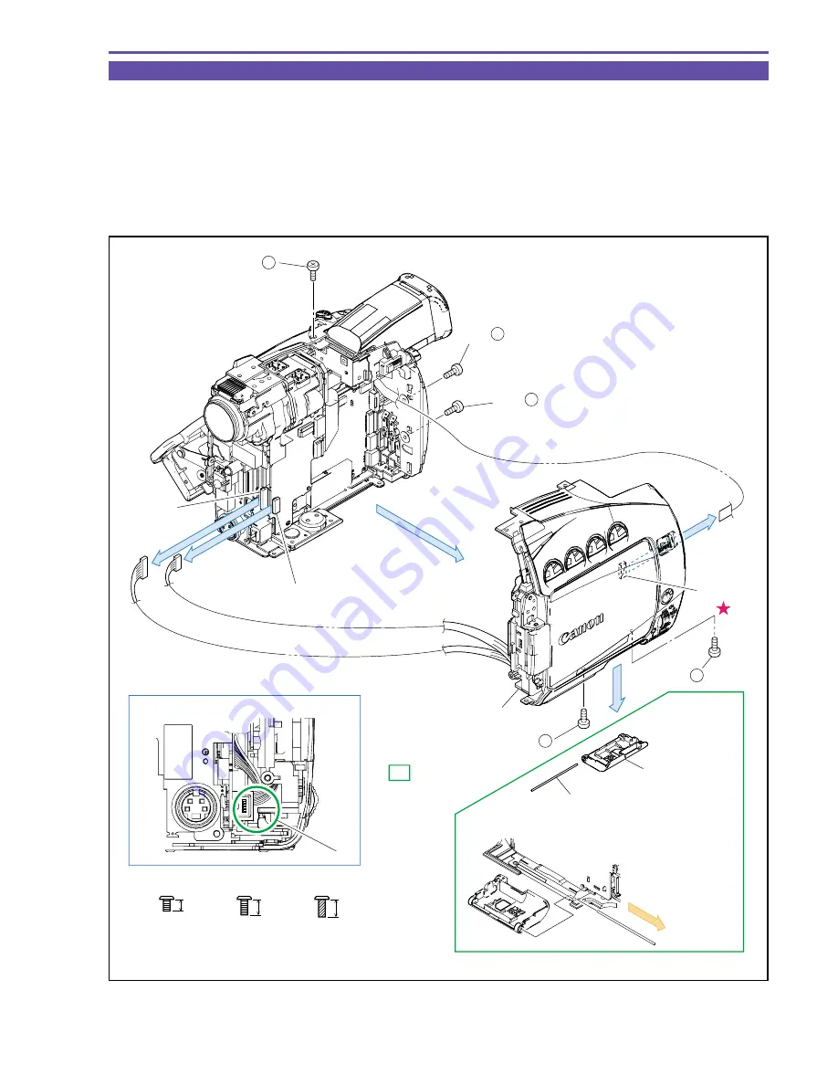
1-4 Separation of Right Cover Unit
(1) Remove five screws (b
×
3, c
×
1, d
×
1), disconnect CN990, CN1502 and CN4001 and detach the Right Cover Unit.
(2) Draw out the Shaft and detach the Card Cover. (Only for ZR70 MC A, ZR65 MC A)
<Note on Reassembling>
(1) Push the CN990 and CN1502 sufficiently so as to prevent them from being pinched in the part A.
(2) Since the Shaft may come out easily, take care not to lose the Shaft. (Only for ZR70 MC A,ZR65 MC A)
Before using the Card Cover and Shaft supplied for repair service, remove their protection sheet and shaft-dropping preventive
tape.
Fig. 4-3
Note on Reassembling (1)
(1) - b
(1) - b
(1) - d
(1)
(1)
(1)
(1)
CN1502
CN990
CN4001
Right Cover Unit
back of the Right Cover Unit
A
(1) - b
Shaft
Shaft remove
Card Cover
(2)
ZR70 MC A
ZR65 MC A
only
(1) - c
3mm
Metal
M1.7
b
4mm
Metal
M1.7
c
4.5mm
Metal
M1.7
(self tap)
d
Summary of Contents for ZR70 MC A
Page 12: ...ZR70 MC A ZR65 MC A ZR60 A CHAPTER 1 GENERAL DESCRIPTION OF PRODUCT 1 9 External View Fig 1 1 ...
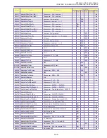
Page 190: ...5 4 ZR70 MC A ZR65 MC A ZR60 A Front Cover Unit Section 4 1 2 6 7 8 3 2 5 3 3 ...
Page 194: ...5 8 ZR70 MC A ZR65 MC A ZR60 A Left Cover Unit Section 2 7 3 2 2 2 2 8 2 5 7 6 9 1 3 4 A A ...
Page 200: ...5 14 ZR70 MC A ZR65 MC A ZR60 A LCD Unit Section 1 3 2 1 3 4 5 10 2 6 7 9 8 ...
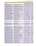
Page 202: ...5 16 ZR70 MC A ZR65 MC A ZR60 A Rear Cover Unit Section 7 4 1 1 3 5 8 6 8 4 2 CVF Unit 1 3 ...
Page 210: ...5 24 ZR70 MC A ZR65 MC A ZR60 A Lens Unit Section 3 2 10 4 5 7 9 8 7 8 1 3 6 2 6 2 ...
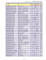
Page 212: ...5 26 DMC III Mechanical Chassis Section 1 1 3 9 5 7 8 6 4 2 3 3 ...
Page 214: ...5 28 DMC III Mechanical Chassis Section 2 1 2 3 4 5 6 7 8 6 1 9 10 13 11 12 ...
Page 216: ...5 30 DMC III Mechanical Chassis Section 3 2 2 2 2 2 3 3 8 9 2 10 11 12 13 4 6 7 5 1 ...
Page 218: ...5 32 DMC III Mechanical Chassis Section 4 1 3 4 5 8 9 6 10 7 2 ...

