ZR70 MC A, ZR65 MC A, ZR60 A
CHAPTER 3. INFORMATION FOR REPAIR · SERVICE HINTS
3-9
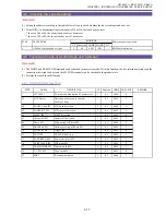
4-2-2 Mechanical Error Analysis Mode
<How to Check>
By following the steps (1) through (4) shown below, the “Sequence” in which the error has occurred can be checked in addition to the
type of the mechanical error.
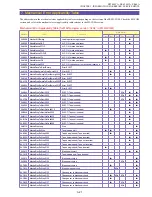
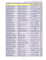
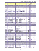
(1) First of all, check the “Sequence” that matches the data (1), referring to “Address” in the mechanical error applicability table.
(2) For the applicable “Sequence” in 1 above, if S reel error detection sensitivity level (CEh or 8Dh) is listed in the “Sreel” subfield of
the “Mecha Error” field, compare it with the data (2). If the data (2) is above the S reel error detection sensitivity level listed, the
error history indication should be “S reel error”.
(3) For the applicable “Sequence” in 1 above, if T reel error detection sensitivity level (CEh or 8Dh) is listed in the “Treel” subfield of
the “Mecha Error” field, compare it with the data (3). If the data (3) is above the T reel error detection sensitivity level listed, the
error history should be “T reel error”.
(4) Unless S or T reel error is determined in step 2 or 3 above, the error history should be the error condition specified in the “Mechani-
cal Error Applicablity Table” field marked with
.
Note :
If a multiple number of items are specified, any of the applicable items should have occurred.
The DEW errors can be identified according to whether or not there is dew indication at an occurrence of an
error.
* The reference table of actual mechanical errors is given at the end of Chapter 3. (See “7: Mechanical Error
Table” on p. 3-21.)
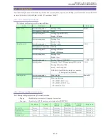
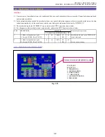
Fig. 3-11
1. Address of the sequence that was under execution
in the event of an error.
(information of the control status.)
2. S reel error detection data in the event of an error.
3. T reel error detection data in the event of an error.
1
3
2
Summary of Contents for ZR70 MC A
Page 12: ...ZR70 MC A ZR65 MC A ZR60 A CHAPTER 1 GENERAL DESCRIPTION OF PRODUCT 1 9 External View Fig 1 1 ...
Page 190: ...5 4 ZR70 MC A ZR65 MC A ZR60 A Front Cover Unit Section 4 1 2 6 7 8 3 2 5 3 3 ...
Page 194: ...5 8 ZR70 MC A ZR65 MC A ZR60 A Left Cover Unit Section 2 7 3 2 2 2 2 8 2 5 7 6 9 1 3 4 A A ...
Page 200: ...5 14 ZR70 MC A ZR65 MC A ZR60 A LCD Unit Section 1 3 2 1 3 4 5 10 2 6 7 9 8 ...
Page 202: ...5 16 ZR70 MC A ZR65 MC A ZR60 A Rear Cover Unit Section 7 4 1 1 3 5 8 6 8 4 2 CVF Unit 1 3 ...
Page 210: ...5 24 ZR70 MC A ZR65 MC A ZR60 A Lens Unit Section 3 2 10 4 5 7 9 8 7 8 1 3 6 2 6 2 ...
Page 212: ...5 26 DMC III Mechanical Chassis Section 1 1 3 9 5 7 8 6 4 2 3 3 ...
Page 214: ...5 28 DMC III Mechanical Chassis Section 2 1 2 3 4 5 6 7 8 6 1 9 10 13 11 12 ...
Page 216: ...5 30 DMC III Mechanical Chassis Section 3 2 2 2 2 2 3 3 8 9 2 10 11 12 13 4 6 7 5 1 ...
Page 218: ...5 32 DMC III Mechanical Chassis Section 4 1 3 4 5 8 9 6 10 7 2 ...

