ZR70 MC A, ZR65 MC A, ZR60 A
CHAPTER 3. INFORMATION FOR REPAIR · SERVICE HINTS
3-19
6-3 Faulty of Playback Picture
<Hints>
In the DV, degradation of picture quality normally appears on the screen as block noise. This is because, if an error occurs exceeding the
ability of the error correction circuit, the block by block information of pictures is not played back properly and thus complemented by
the previous picture information. Normally, such block noise appears on the screen when the error rate has considerably been degraded
due to the degraded tape or the lowered head output, etc. Be sure to check the playback picture quality by the error rate.
<Check Points>
1)
Deterioration of Tape Quality
Check if flaws, kinks, etc. are found on a magnetic face of tape or not, and compare it with the error rate of other unit.
2)
Error Rate (P. 3-7)
In the service mode, check an error rate of self-recording/LP playback. The specified allowable error rate is 2
×
10
-5
.
In case of NG, take the following procedure.
(1) Observe a playback envelope. If it is abnormal, carry out tape-path adjustment.
(2) Run a cleaning tape.
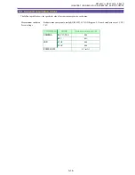
Use the cleaning tape of hard type (DY9-1384-000).
[Playback time]
Hard cleaning tape (DY9-1384-000)
: After replacement of the drum unit
→
25 seconds
For cleaning
→
25 seconds per time, Up to three times
* When using hard-type cleaning tape, select the cleaning mode on the product main unit.
(Refer to 4-3 - Cleaning Mode, p. 3-10.)
(3) Check the error rate again.
If the error rate is out of the specified range, clean the tape drive parts (posts, drum) using cleaning paper moistened with
alcohol.
* Take care not to damage the head.
* Do not touch the head with bare hand.
(4) Check the error rate again.
If the error rate is out of the specified range, replace the tape with a new one and check the error rate again. At this step, use a
tape (must be Panasonic LP tape) which has been purchased at a different time. The error rate may become worse due to
inconsistent quality or aging of the tape.
(5) Check the error rate again.
If the error rate is out of the specified range, replace the drum unit.
(6) Check the error rate again.
If the error rate is out of the specified range, replace the mechanical unit.
Summary of Contents for ZR70 MC A
Page 12: ...ZR70 MC A ZR65 MC A ZR60 A CHAPTER 1 GENERAL DESCRIPTION OF PRODUCT 1 9 External View Fig 1 1 ...
Page 190: ...5 4 ZR70 MC A ZR65 MC A ZR60 A Front Cover Unit Section 4 1 2 6 7 8 3 2 5 3 3 ...
Page 194: ...5 8 ZR70 MC A ZR65 MC A ZR60 A Left Cover Unit Section 2 7 3 2 2 2 2 8 2 5 7 6 9 1 3 4 A A ...
Page 200: ...5 14 ZR70 MC A ZR65 MC A ZR60 A LCD Unit Section 1 3 2 1 3 4 5 10 2 6 7 9 8 ...
Page 202: ...5 16 ZR70 MC A ZR65 MC A ZR60 A Rear Cover Unit Section 7 4 1 1 3 5 8 6 8 4 2 CVF Unit 1 3 ...
Page 210: ...5 24 ZR70 MC A ZR65 MC A ZR60 A Lens Unit Section 3 2 10 4 5 7 9 8 7 8 1 3 6 2 6 2 ...
Page 212: ...5 26 DMC III Mechanical Chassis Section 1 1 3 9 5 7 8 6 4 2 3 3 ...
Page 214: ...5 28 DMC III Mechanical Chassis Section 2 1 2 3 4 5 6 7 8 6 1 9 10 13 11 12 ...
Page 216: ...5 30 DMC III Mechanical Chassis Section 3 2 2 2 2 2 3 3 8 9 2 10 11 12 13 4 6 7 5 1 ...
Page 218: ...5 32 DMC III Mechanical Chassis Section 4 1 3 4 5 8 9 6 10 7 2 ...

