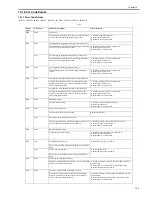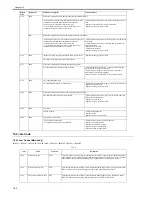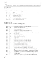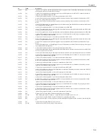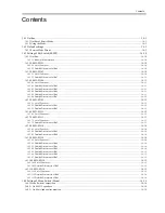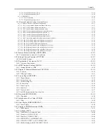
Contents
16.4.4 <No.007 ATT transmission level> ........................................................................................................................................ 16-16
16.4.5 <No.008 V.34 modulation speed upper limit> ...................................................................................................................... 16-16
16.4.6 <No.009 V.34 data speed upper limit>.................................................................................................................................. 16-16
16.4.7 <No.010 Frequency of the pseudo CI signal> ....................................................................................................................... 16-17
16.5 Setting of Numeric Parameter (NUMERIC Param.)............................................................................................... 16-17
16.5.1 Numerical Parameter Composition........................................................................................................................................ 16-17
16.5.2 <002: RTN transmission condition (1)><003: RTN transmission condition (2)><004: RTN transmission condition (3)>. 16-17
16.5.3 <005: NCC pause length (pre-ID code)>............................................................................................................................... 16-18
16.5.4 <006: NCC pause length (post-ID code)> ............................................................................................................................. 16-18
16.5.5 <010: line connection identification length> ......................................................................................................................... 16-18
16.5.6 <011: T.30 T1 timer (for reception)> .................................................................................................................................... 16-18
16.5.7 <013: T.30 EOL timer> ......................................................................................................................................................... 16-18
16.5.8 <015: hooking detection time> .............................................................................................................................................. 16-18
16.5.9 <016: time length to first response at time of fax/tel switchover> ........................................................................................ 16-18
16.5.10 <017: pseudo RBT signal pattern ON time length><018: pseudo RBT signal pattern OFF time length (short)><019: pseudo
RBT signal pattern OFF time length (long)> ............................................................................................................................... 16-18
16.5.11 <020: pseudo CI signal pattern ON time length><021: pseudo CI signal pattern OFF time length (short)><022: pseudo CI
signal pattern OFF time length (long)> ........................................................................................................................................ 16-18
16.5.12 <023: CNG detention level for fax/tel switchover> ............................................................................................................ 16-18
16.5.13 <024: pseudo RBT transmission level at time of fax/tel switchover>................................................................................. 16-18
16.5.14 <025: Answering machine connection function signal detection time>.............................................................................. 16-18
16.5.15 <027: V.21 low-speed flag preamble identification length> ............................................................................................... 16-18
16.5.16 <056 - 061: Count type select >........................................................................................................................................... 16-19
16.6 Setting of Scanner Functions (SCANNER) ............................................................................................................ 16-22
16.6.1 Numeric Parameter Functional configuration........................................................................................................................ 16-22
16.6.2 <024:CIS scan position during ADF scanning> .................................................................................................................... 16-23
16.6.3 <026:Distance from the standby position of CIS to the shading start point>........................................................................ 16-23
16.6.4 <031: Vertical scan start position adjustment>...................................................................................................................... 16-23
16.6.5 <032: Horizontal scan start position adjustment> ................................................................................................................. 16-23
16.6.6 <033: Vertical scan magnification correction> ..................................................................................................................... 16-23
16.6.7 <034: Horizontal scan magnification correction> ................................................................................................................. 16-23
16.6.8 <035: - 036:Reader motor speed change> ............................................................................................................................. 16-23
16.6.9 <041: Vertical scan start position adjustment (when scanning on a document fed from ADF)>.......................................... 16-23
16.6.10 <042: Horizontal scan start position adjustment (when scanning on a document fed from ADF)> ................................... 16-23
16.6.11 <043: Horizontal scan end position correction ((copy:scanning on ADF)>........................................................................ 16-23
16.6.12 <044: Horizontal scan end position correction (superfine:scanning on ADF)> .................................................................. 16-23
16.6.13 <045: Horizontal scan end position correction (fine:scanning on ADF)>........................................................................... 16-24
16.6.14 <046: Horizontal scan end position correction (standard:scanning on ADF)> ................................................................... 16-24
16.6.15 <047: Vertical scan magnification correction (when scanning on a document fed from ADF)> ....................................... 16-24
16.6.16 <048: Horizontal scan magnification correction (when scanning on a document fed from ADF)> ................................... 16-24
16.6.17 <054: Pickup motor speed correction (when the ADF is used) >........................................................................................ 16-24
16.6.18 <193: ADF special standard-sized paper: LGL misidentification-ready>........................................................................... 16-24
16.6.19 <194: ADF special standard-sized paper: LTR misidentification-ready>........................................................................... 16-24
16.6.20 <195: ADF special standard-sized paper: LTR_R misidentification-ready> ...................................................................... 16-24
16.6.21 <213: XYZ correction value (X) of standard white plate> (equipped with SEND functions) ............................................ 16-24
16.6.22 <214: XYZ correction value (Y) of standard white plate> (equipped with SEND functions) ............................................ 16-25
16.6.23 <215: XYZ correction value (Z) of standard white plate> (equipped with SEND functions) ............................................ 16-25
16.7 Setting of Printer Functions (PRINTER) ................................................................................................................ 16-25
16.7.1 Service Soft Switch Settings (PRINTER).............................................................................................................................. 16-25
16.7.1.1 SSSW-SW05............................................................................................................................................................................................. 16-25
16.7.1.1.1 List of Functions ............................................................................................................................................................................... 16-25
16.7.1.1.2 Detailed Discussions of Bit 7............................................................................................................................................................ 16-25
16.7.1.2 SSSW-SW14............................................................................................................................................................................................. 16-26
16.7.1.2.1 List of Functions ............................................................................................................................................................................... 16-26
16.7.1.2.2 Detailed Discussions of Bit 0............................................................................................................................................................ 16-26
16.7.1.2.3 Detailed Discussions of Bit 2............................................................................................................................................................ 16-26
16.7.1.2.4 Detailed Discussions of Bit 4............................................................................................................................................................ 16-26
Summary of Contents for iR1020 Series
Page 1: ...Sep 1 2008 Service Manual iR1020 1021 1024 1025 Series ...
Page 2: ......
Page 6: ......
Page 17: ...Chapter 1 Introduction ...
Page 18: ......
Page 20: ......
Page 49: ...Chapter 1 1 29 ...
Page 50: ......
Page 51: ...Chapter 2 Installation ...
Page 52: ......
Page 54: ......
Page 61: ...Chapter 2 2 7 ...
Page 62: ......
Page 63: ...Chapter 3 Basic Operation ...
Page 64: ......
Page 66: ......
Page 73: ...Chapter 3 3 7 ...
Page 74: ......
Page 75: ...Chapter 4 Original Exposure System ...
Page 76: ......
Page 78: ......
Page 87: ...Chapter 5 Laser Exposure ...
Page 88: ......
Page 90: ......
Page 94: ......
Page 95: ...Chapter 6 Image Formation ...
Page 96: ......
Page 98: ......
Page 103: ...Chapter 7 Pickup Feeding System ...
Page 104: ......
Page 106: ......
Page 120: ......
Page 121: ...Chapter 8 Fixing System ...
Page 122: ......
Page 124: ......
Page 135: ...Chapter 9 External and Controls ...
Page 136: ......
Page 138: ......
Page 151: ...Chapter 10 Original Feeding System ...
Page 152: ......
Page 154: ......
Page 156: ...Chapter 10 10 2 M2001 ADF motor Symbol Name ...
Page 170: ......
Page 171: ...Chapter 11 e maintenance imageWARE Remote ...
Page 172: ......
Page 174: ......
Page 184: ......
Page 185: ...Chapter 12 Maintenance and Inspection ...
Page 186: ......
Page 188: ......
Page 190: ......
Page 191: ...Chapter 13 Standards and Adjustments ...
Page 192: ......
Page 194: ......
Page 201: ...Chapter 14 Correcting Faulty Images ...
Page 202: ......
Page 204: ......
Page 214: ......
Page 215: ...Chapter 15 Self Diagnosis ...
Page 216: ......
Page 218: ......
Page 224: ......
Page 225: ...Chapter 16 Service Mode ...
Page 226: ......
Page 230: ......
Page 232: ...Chapter 16 16 2 Makes various status checks such as contact sensor sensor and print status ...
Page 278: ......
Page 279: ...Chapter 17 Upgrading ...
Page 280: ......
Page 282: ......
Page 297: ...Chapter 18 Service Tools ...
Page 298: ......
Page 299: ...Contents Contents 18 1 Service Tools 18 1 18 1 1 Special Tools 18 1 ...
Page 300: ......
Page 302: ......
Page 303: ...Sep 1 2008 ...
Page 304: ......


