


Chapter 13
13-4
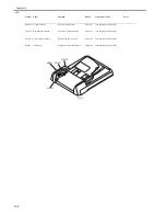
13.4 ADF
13.4.1 Outline
13.4.1.1 Outline
0013-1273
iR1020J / iR1024J / iR1020 / iR1024 / iR1024A / iR1024N / iR1024F /
iR1024i / iR1024iF
This machine has the following adjustment items. Make the necessary ad-
justments after replacing each part.
T-13-3
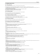
13.4.1.2 Preparing a Test Sheet for Adjustment
0013-1274
iR1020J / iR1024J / iR1020 / iR1024 / iR1024A / iR1024N / iR1024F /
iR1024i / iR1024iF
Preparing a Test Sheet: On a sheet of A4 or LTR paper, draw straight lines
as indicated:
F-13-7
F-13-8
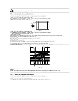
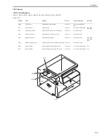
13.4.2 Adjusting the Mechanical System
13.4.2.1 Adjusting the Perpendicularity
0013-1276
iR1020J / iR1024J / iR1020 / iR1024 / iR1024A / iR1024N / iR1024F /
iR1024i / iR1024iF
1) reate a test chart, load it in the ADF, and make a copy of it.
2) Compare the lines at the end of the test chart with those on the copy for
perpendicularity. Measure dimensions A and B at the end of the copy and
adjust the amount of skew (the range shown in the table) to within the
spec.
T-13-4
F-13-9
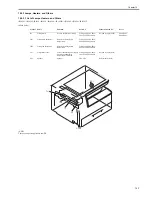
3) Loosen the two screws [1] securing the right hinge and slide the hinge ac-
cording to the sale markings so that the perpendicularity is within spec.
F-13-10
4) Tighten the screws you loosened in step 3.
13.4.3 Adjusting the Ellectrical System
13.4.3.1 Adjusting the Magnification
0013-1277
iR1020J / iR1024J / iR1020 / iR1024 / iR1024A / iR1024N / iR1024F /
iR1024i / iR1024iF
1) Create a test chart, load it in the ADF, and make a copy of it. This copy is
called copy A.
2) Compare the longitudinal image length on the test chart with that on copy
A. If required, make an adjustment in the service mode.
(A4-size paper: 277 +/-1mm LTR paper: 59 +/-1mm)
Image on copy A is shorter. -> Increase the value (or reduce the stream read-
ing speed).
Image on copy A is longer. -> Decrease the value (or increase the stream
reading speed).
3) Enter the service mode.
Sequentially press the additional functions key, 2 key, 8 key, and additional
functions key on the operation panel of the host machine.
4) Using the arrow keys on the operation panel, display "#SCAN".
5) Press the OK key.
6) Using the arrow keys on the operation panel, display "#SCAN NUMER-
IC".
7) Press the OK key.
8) Using the arrow keys, select "48".
9) Using the numeric keys, change the value to determine the optimum value.
Next, press the OK key. (Default: 32)
No.
Adjustment type
Replaced parts
[1]
Perpendicularity adjustment Hinge
[2]
Magnification adjustment
Motor/roller
[3]
Side registration adjustment -
[4]
Leading edge registration
adjustment
-
Dimension
(using A4)
Dimension
(using LTR)
A-B
0 +/- 1.5 mm
0 +/- 1.5 mm
10mm
10mm
10mm
10mm
<Using A4 Paper>
Draw straight lines.
(feeding direction)
10mm
210mm
297mm
10mm
10mm
10mm
10mm
<Using LTR Paper>
Draw straight lines.
(feeding direction)
10mm
216mm
279mm
Copy of the test sheet
A
B
(feeding direction)
[1]
Summary of Contents for iR1020 Series
Page 1: ...Sep 1 2008 Service Manual iR1020 1021 1024 1025 Series ...
Page 2: ......
Page 6: ......
Page 17: ...Chapter 1 Introduction ...
Page 18: ......
Page 20: ......
Page 49: ...Chapter 1 1 29 ...
Page 50: ......
Page 51: ...Chapter 2 Installation ...
Page 52: ......
Page 54: ......
Page 61: ...Chapter 2 2 7 ...
Page 62: ......
Page 63: ...Chapter 3 Basic Operation ...
Page 64: ......
Page 66: ......
Page 73: ...Chapter 3 3 7 ...
Page 74: ......
Page 75: ...Chapter 4 Original Exposure System ...
Page 76: ......
Page 78: ......
Page 87: ...Chapter 5 Laser Exposure ...
Page 88: ......
Page 90: ......
Page 94: ......
Page 95: ...Chapter 6 Image Formation ...
Page 96: ......
Page 98: ......
Page 103: ...Chapter 7 Pickup Feeding System ...
Page 104: ......
Page 106: ......
Page 120: ......
Page 121: ...Chapter 8 Fixing System ...
Page 122: ......
Page 124: ......
Page 135: ...Chapter 9 External and Controls ...
Page 136: ......
Page 138: ......
Page 151: ...Chapter 10 Original Feeding System ...
Page 152: ......
Page 154: ......
Page 156: ...Chapter 10 10 2 M2001 ADF motor Symbol Name ...
Page 170: ......
Page 171: ...Chapter 11 e maintenance imageWARE Remote ...
Page 172: ......
Page 174: ......
Page 184: ......
Page 185: ...Chapter 12 Maintenance and Inspection ...
Page 186: ......
Page 188: ......
Page 190: ......
Page 191: ...Chapter 13 Standards and Adjustments ...
Page 192: ......
Page 194: ......
Page 201: ...Chapter 14 Correcting Faulty Images ...
Page 202: ......
Page 204: ......
Page 214: ......
Page 215: ...Chapter 15 Self Diagnosis ...
Page 216: ......
Page 218: ......
Page 224: ......
Page 225: ...Chapter 16 Service Mode ...
Page 226: ......
Page 230: ......
Page 232: ...Chapter 16 16 2 Makes various status checks such as contact sensor sensor and print status ...
Page 278: ......
Page 279: ...Chapter 17 Upgrading ...
Page 280: ......
Page 282: ......
Page 297: ...Chapter 18 Service Tools ...
Page 298: ......
Page 299: ...Contents Contents 18 1 Service Tools 18 1 18 1 1 Special Tools 18 1 ...
Page 300: ......
Page 302: ......
Page 303: ...Sep 1 2008 ...
Page 304: ......


