Chapter 1
1-21
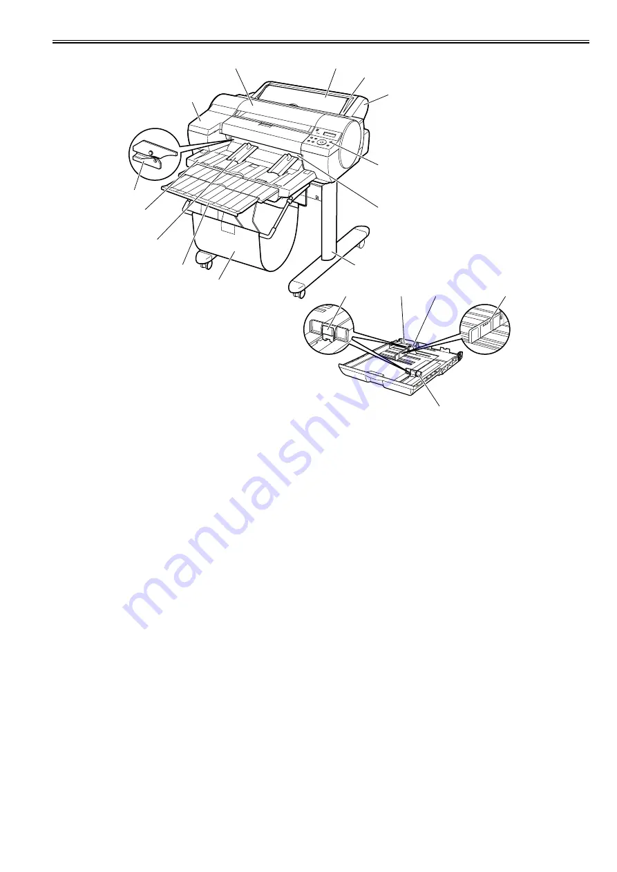
F-1-28
[1] Top cover
Open this cover when installing the printhead or remove the media jammed inside the printer.
[2] Ink tank cover
Open this cover when replacing ink tanks.
[3] Cutter
A round-blade cutter cuts roll media automatically. It is stowed inside when it is out of use.
[4] Output tray
Printed documents are ejected into the output tray.
[5] Output guides
These guides support printed documents as they are ejected, preventing jams. Raise the guides before printing on rolls.
[6] Output tray extension
An extension to prevent ejected paper from falling to the floor. Pull out the extension to match the paper size before printing on sheets.
[7] Basket
Receives printed matter as it is ejected. Only one sheet can be housed in the basket.
[8] Stand
The base on which the printer is mounted. The stand equipped with casters is easy to move.
[9] Paper eject slot (paper tray front loading port)
All printed matter is ejected from this port. In loading thick paper, insert it into this port.
[10] Operation panel
Contains the power button, online button display and so on.
[11] Roll feed unit
Load roll media on this unit.
[12] Roll feed unit cover
Load roll media with this cover open.
[13] Paper tray cover
Load cut sheet at the paper tray top loading port with this cover open. This cover is opened, and the cut sheet is set at top manual feed slot.
[14] Cassette
Load sheets in this tray.
[15] Guide lever
Squeeze these levers to slide the guides.
[16] Length guide
Adjust this guide to hold paper lengthwise.
[17] Maximum capacity line
A guide line indicating how many sheets can be loaded. Do not load paper over this line.
[18] Width guide
Adjust this guide to hold paper widthwise.
[1]
[13]
[12]
[2]
[10]
[11]
[7]
[4]
[5]
[6]
[9]
[8]
[17]
[18]
[14]
[16]
[15]
[3]
Summary of Contents for iPF5000 - imagePROGRAF Color Inkjet Printer
Page 1: ...May 24 2007 Service Manual iPF5000 series ...
Page 2: ......
Page 6: ......
Page 12: ...Contents 8 3 Sevice Call Table 8 4 8 3 1 Service Call Errors 8 4 ...
Page 13: ...Chapter 1 PRODUCT DESCRIPTION ...
Page 14: ......
Page 20: ...Chapter 1 1 4 F 1 5 ...
Page 80: ...Chapter 1 1 64 ...
Page 81: ...Chapter 1 1 65 ...
Page 82: ......
Page 83: ...Chapter 2 TECHNICAL REFERENCE ...
Page 84: ......
Page 156: ......
Page 157: ...Chapter 3 INSTALLATION ...
Page 158: ......
Page 160: ......
Page 205: ...Chapter 4 DISASSEMBLY REASSEMBLY ...
Page 206: ......
Page 208: ......
Page 264: ...Chapter 4 4 56 ...
Page 283: ...Chapter 5 MAINTENANCE ...
Page 284: ......
Page 286: ......
Page 293: ...Chapter 6 TROUBLESHOOTING ...
Page 294: ......
Page 354: ......
Page 355: ...Chapter 7 SERVICE MODE ...
Page 356: ......
Page 358: ......
Page 379: ...Chapter 8 ERROR CODE ...
Page 380: ......
Page 382: ......
Page 388: ......
Page 389: ...May 24 2007 ...
Page 390: ......


