Chapter 4
4-63
4.3.22 Draining the Ink
0012-6416
iPF5000 / iPF5100
There are two methods of removing the ink, amanual methtod and an automatic method.
There the ink is drained, the ink inside the ink passage totaling about72g(about 6g x 12colors) is drained as waste ink.
To prevent ink leakage, be sure to drain the ink inside the ink passage before transporting the printer again.
1. Automatic ink drainage
To perform "automatic ink drainage", select "Main Menu" > "Maintenance" > "Move Printer".
Perform automatic ink drainage again if a power outage or other cause shuts off the power during the operation for automatic ink drainage.
2. Manual Ink Drainage
Perform manual ink drainage when the printer cannot be powered due to a printer's electrcal part failure, firmware error, or power supply problem.
Manual Ink Drainage Procedure
1) Open the top cover, and then remove the left and right circle covers, tank cover, right upper cover, operation panel, mist filter, filter cover, filter, and right cover.
Refer to DISASSEMBLY/REASSEMBLY > Pointe toNote on Disassembly andReassembly > External Cover.
2) Move the carriage onto the platen.
Refer to DISASSEMBLY/REASSEMBLY > Points to Note on Disassembly and Reassembly > Opening the Cap/
Move the Wiper Unit.
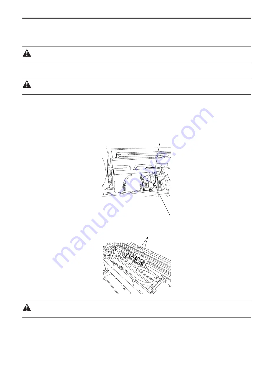
3) Turn the cam[2] in the direction of the arrow, and then press the link[1] to open the ink supply valve.
F-4-154
4) Release both printhead fixer levers[1] to flow the ink from inside the ink tube to the sub-buffer of the ink tank unit.
F-4-155
The sub-buffer can contain 22g of ink. About 6g of ink flows into the sub-buffer each time manual ink drainage is performed.
5) Make sure that the ink has been drained completely, turn the cam to close the ink supply valve.
[1]
[2]
[1]
Summary of Contents for iPF5000 - imagePROGRAF Color Inkjet Printer
Page 1: ...May 24 2007 Service Manual iPF5000 series ...
Page 2: ......
Page 6: ......
Page 12: ...Contents 8 3 Sevice Call Table 8 4 8 3 1 Service Call Errors 8 4 ...
Page 13: ...Chapter 1 PRODUCT DESCRIPTION ...
Page 14: ......
Page 20: ...Chapter 1 1 4 F 1 5 ...
Page 80: ...Chapter 1 1 64 ...
Page 81: ...Chapter 1 1 65 ...
Page 82: ......
Page 83: ...Chapter 2 TECHNICAL REFERENCE ...
Page 84: ......
Page 156: ......
Page 157: ...Chapter 3 INSTALLATION ...
Page 158: ......
Page 160: ......
Page 205: ...Chapter 4 DISASSEMBLY REASSEMBLY ...
Page 206: ......
Page 208: ......
Page 264: ...Chapter 4 4 56 ...
Page 283: ...Chapter 5 MAINTENANCE ...
Page 284: ......
Page 286: ......
Page 293: ...Chapter 6 TROUBLESHOOTING ...
Page 294: ......
Page 354: ......
Page 355: ...Chapter 7 SERVICE MODE ...
Page 356: ......
Page 358: ......
Page 379: ...Chapter 8 ERROR CODE ...
Page 380: ......
Page 382: ......
Page 388: ......
Page 389: ...May 24 2007 ...
Page 390: ......


