


COPYRIGHT © 2001 CANON INC. CANON CLC1000/1000S/3100 REV.2 MAY 2001 PRINTED IN JAPAN (IMPRIME AU JAPON)
3-193
3. OPERATION AND TIMING
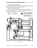
2. LCD Display Processing
The CPU on the reader controller PCB sends commands to the LCD controller at such times as
programmed in advance. The LCD controller, on the other hand, interprets and executes these commands.
The LCD controller performs ON/OFF control over the display as programmed.
The LCD controller writes display character codes in the RAM for display memory in sequence; the RAM
data is then displayed on the display panel in response to the timing signal generated by the LCD controller.
3. Adjusting the LCD Contrast
VR5301 is mounted on the control panel relay PCB and may be used to adjust the contrast of the LCD
panel.
Figure 3-702
Control panel
LCD panel (200x640)
Tenkey/subkey PCB
Pilot lamp PCB
Control panel relay PCB
VR5301
LCD controller
CPU
Display memory
RAM
Reader controller PCB
Summary of Contents for 1000S
Page 12: ......
Page 30: ......
Page 44: ......
Page 86: ......
Page 254: ......
Page 372: ......
Page 374: ......
Page 418: ......
Page 438: ......
Page 442: ......
Page 754: ......
Page 764: ......
Page 766: ......
Page 840: ...0501GR PRINTED IN JAPAN IMPRIME AU JAPON This publication is printed on 100 reprocessed paper ...