


3. OPERATION AND TIMING
COPYRIGHT © 2001 CANON INC. CANON CLC1000/1000S/3100 REV.2 MAY 2001 PRINTED IN JAPAN (IMPRIME AU JAPON)
3-104
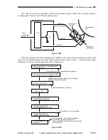
Figure 3-529 shows the circuit that controls the developing bias, and the circuit has the following
functions:
HVT3B
• Generates high voltage for AC bias
• Generates timing signals for AC bias generation
HVT3A
• Turns on and off the DC bias
• Generates AC bias
• Turns on and off the AC bias
• Controls the voltage for DC bias
The AC bias is generated and turned on/off as follows:
Transformer drive signal HVON=1 and developing AC bias enable signal HVACEN=1
The transformer is driven, and ±1kV is sent to the AC bias generation circuit.
An AC bias is generated based on signals from the timing generation circuit.
When the AC bias output signal HVAC=1, the AC bias is applied to each
developing cylinder.
Figure 3-529
HVT3A (front)
HVT3B
DC controller PCB
AC bias
generation
circuit
Voltage
control circuit
Transformer for DC
+1kV
HVDCEN-C
HVDC-C
HVDCEN-M
HVDC-M
HVAC-C
HVAC-M
24V
HVACEN
HVON
-1kV
Timing signal generation
Transformer for
+1kV
Transformer for -1kV
For C
For Bk
For Y
For M
Voltage
control circuit
HVT3A (rear) (same as HVT3A (front))
AC bias
DC bias
Summary of Contents for 1000S
Page 12: ......
Page 30: ......
Page 44: ......
Page 86: ......
Page 254: ......
Page 372: ......
Page 374: ......
Page 418: ......
Page 438: ......
Page 442: ......
Page 754: ......
Page 764: ......
Page 766: ......
Page 840: ...0501GR PRINTED IN JAPAN IMPRIME AU JAPON This publication is printed on 100 reprocessed paper ...