3. OPERATION AND TIMING
COPYRIGHT © 2001 CANON INC. CANON CLC1000/1000S/3100 REV.2 MAY 2001 PRINTED IN JAPAN (IMPRIME AU JAPON)
3-108
b.
Measuring the Color Toner Density
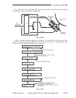
The Y, M, and C developing assemblies each are equipped with a color toner density sensor inside them
(Figure 3-535), and each sensor is used to measure the density of toner retained on its respective cylinder.
Figure 3-535
The mechanism of measurement is as follows:
The CLC1000’s developer is a two-component developer consisting of carrier and toner. When exposed
to infrared light, the color toner will reflect infrared light while the carrier will absorb it. In other words, when the
amount of toner decreases because of consumption over time, the reflection of infrared light will decrease
because of the changing toner/carrier ratio of the developer.
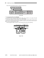
Using an infrared diode, the toner/carrier ratio
is computed from the intensity of the infrared light
reflected by the developer on the developing
cylinder.
To make up for the deterioration occurring in
the infrared diode and changes in temperature, the
direct light is also measured at the same time.
Figure 3-536
Y
M
C
CL
Bk
Color toner density sensor
DC controller PCB
Toner supply signal
Transfer belt
Toner supply clutch
Developing
cylinder
Direct intensity/reflected intensity signal
Detection of direct light
Mirror
Cylinder
Detection of
reflected light
LED
Direct intensity signal
Reflected intensity signal
Summary of Contents for 1000S
Page 12: ......
Page 30: ......
Page 44: ......
Page 86: ......
Page 254: ......
Page 372: ......
Page 374: ......
Page 418: ......
Page 438: ......
Page 442: ......
Page 754: ......
Page 764: ......
Page 766: ......
Page 840: ...0501GR PRINTED IN JAPAN IMPRIME AU JAPON This publication is printed on 100 reprocessed paper ...


