3. OPERATION AND TIMING
COPYRIGHT © 2001 CANON INC. CANON CLC1000/1000S/3100 REV.2 MAY 2001 PRINTED IN JAPAN (IMPRIME AU JAPON)
3-64
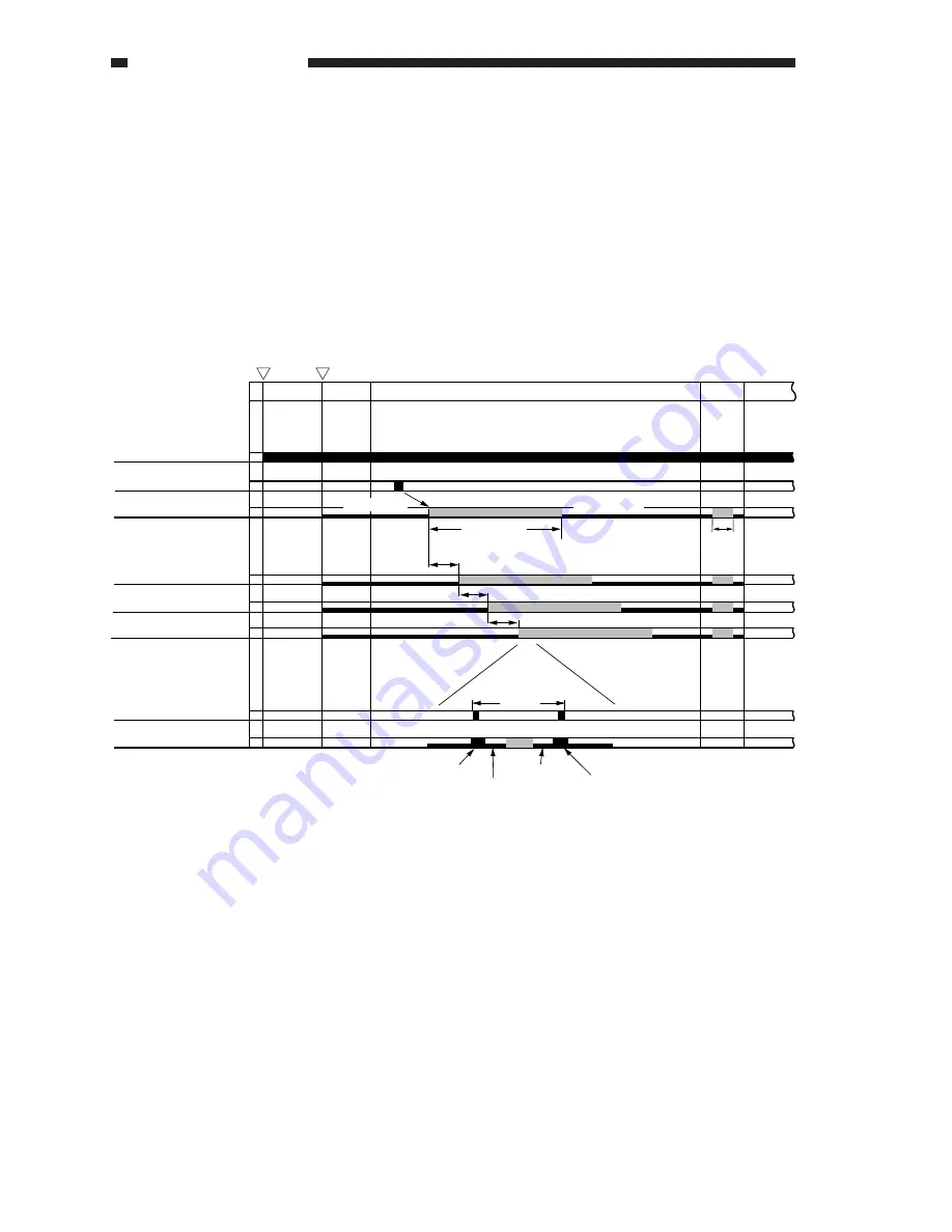
B. Sequence of Operations (laser exposure system)
Figure 3-404 shows the sequence of operations for the laser exposure system.
The laser scanner motor starts to rotate as soon as the power switch is turned on and continues to rotate
at a specific speed until the power switch is turned off.
Each semiconductor laser is 00-activated as soon as the Start key is pressed and is PWM-activated in
relation to the image leading edge signal to form a latent image on the drum. The PWM activation period is
given a delay for each color to make up for the distance between drums.
When the PWM activation for a single scan ends, the laser turns fully for BD signal detection; the next
scanning operation starts when the BD signal is generated.
Figure 3-404
Laser scanner motor
Image leading edge signal (ITOP)
BD signal
Y laser
M laser
C laser
Bk laser
Bk laser
(*1) if only executed SALT control
COPY
Drum distance
SALT
*1
Power switch ON
Start key ON
CNTR
LSTR
STBY
PWM activation
PWM activation
Full activation
Full activation
Paper length
1 scan
00 activation
00 activation
00 activation
00 activation
Summary of Contents for 1000S
Page 12: ......
Page 30: ......
Page 44: ......
Page 86: ......
Page 254: ......
Page 372: ......
Page 374: ......
Page 418: ......
Page 438: ......
Page 442: ......
Page 754: ......
Page 764: ......
Page 766: ......
Page 840: ...0501GR PRINTED IN JAPAN IMPRIME AU JAPON This publication is printed on 100 reprocessed paper ...


