background image

11

SYSTEM 2316E/2316EC  Installation Manual

Programming Hexadecimal Numbers

Data  is  programmed  into  the  panel  using  the  hexadecimal  number

system, which consists of the digits 0 - 9 and the letters A - F. The digits

0 - 9 are entered directly from the keypad. The chart below shows how

to enter the hexadecimal digits A through F.

The same procedure is used with both the LED and the Alpha Plus

keypads.

End of Programming Segment

The last two Command Locations are CL 68 and B4. When you press the

[#] key at these locations, the program will advance to CL 69 or CL B5,

respectively.  These  locations  are  not  used  in  the  SYSTEM  2316E/

2316EC.  If  you  enter  CL  69  or  CL  B5,  either  press  [*]  [#]  to  exit

programming, or press the Command Location number and [#] for the

programming  location  you  want.  (Remember  when  using  the  LED

keypad to enter the Command Location, the Data, then the [#] key.)

PROGRAMMING THE ALPHA Plus KEYPAD

In order to program the Alpha Plus keypad, you must have it wired to

the  SYSTEM  2316E/2316EC,  have  power  applied  to  the  panel,  and

have the keypad properly addressed. 

You can only program when

the  panel  is  disarmed

.

NOTE:

Programming The Keypad is NOT the same as Keypad

Programming.  (Keypad  programming  is  used  to  program  the

control  panel.)

To  Exit  Panel  Programming

When you have finished programming, press [*] [#].  The panel will

also exit the programming mode if you do not press any key within a

five minute period.

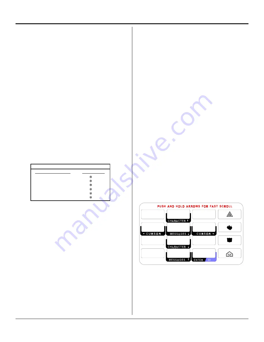
Keypad  Message  Programming

The Alpha keypad programming template is used to allow the installer

to  program  messages  and  zone  descriptions  into  the  Alpha  Plus

keypads. The template (see Figure 11 below) should be used when

programming  the  keypad.
To activate the keypad programming mode, enter the [Installer's Code]

[*]  [0]  [1]  [#].  Information  may  be  entered  into  the  keypad  in  the

form of letters (upper and lower case), numbers (0 - 9), and 22 spe-

cial symbols. All characters are displayed in the order listed above,

such  as  upper  and  lower  case  letters,  numbers,  and  special  sym-

bols.  The  [Space]  character  precedes  the  letter  A.
To enter a Message or Label, use the [2] key to scroll through the

characters until you reach the desired character. If you scroll past the

desired character, the [8] key may be used to scroll backwards. When

the desired character is displayed, press the [6] key to move the cursor

to the next character position. The [4] key moves the cursor to the

left. When all characters have been entered, press the [#] key to write

the message and move to the next message position. Use the [0] key

to move backward through the messages.
The  message  order  is  as  follows:

• SERVICE  MESSAGE

• DEALER  MESSAGE

• SOFT ZONE IDENTIFIERS (A, B, and C)

• HARDWIRED  LOOP  IDENTIFIERS

• KEYPAD  ADDRESS

You can program the Alpha Plus keypads for special messages, each

of the 16 zone labels, and the keypad address. 

Zone Labels

 display

during  the  walk-test  and  when  the  [#]  key  is  pressed  during  alarm

memory or faults. The programmable 

Service Message

 is displayed

during AC failure, fuse failure, communication failure, or low battery. The

Dealer Message

 displays when the system is disarmed. The keypad

address is initially displayed only during system start up (see page 8,

Addressing Alpha Plus Keypads).
These  messages  can  be  programmed  directly  from  the  Alpha  Plus

keypad or remotely using the COMMANDER II/MONITOR II software

package. For more detailed information about remote programming,

refer to the COMMANDER II/MONITOR II Operating Manual.

To  exit  Alpha  Plus  Keypad  Programming

When you have finished programming, press [*] [#]. 

The keypad will

also exit the programming mode if you do not press any key within a

five minute period.

Figure 11

ALPHA PLUS  Programming  Template

1

2

3

6

5

4

7

8

9

0

7

Programming with the Alpha Plus Keypad

Entering program data with an Alpha Plus keypad is a two-step process.

First, key in the two-digit address (Command Location) to be programmed

and  press  the  [#]  key.  The  Alpha  Plus  keypad  will  display  the  value

previously programmed into that location. Then enter the data you wish

stored at that location and press the [#] key to store the data. You can also

scroll through the Command Locations in numerical order by alternately

pressing and releasing the [#] key.

NOTE:

Command Locations A0, B3, and B4 must be addressed

directly.  The  data  stored  at  these  locations  is  not  displayed.  To

program them: Enter the Command Location and press the [#] key.

Enter the data to be stored and again press the [#] key.

PROGRAMMING  CONVERSIONS

Hexadecimal Value

Key Strokes

A

B

C

D

E

F

0

1

2

3

4

5

Programming with the LED Plus Keypad

Programming with an LED Plus keypad is a one-step process. Key in the

two-digit  address  (Command  Location),  followed  immediately  by  the

desired programming values (program data). Press the [#] key to store

the data. The LED Plus keypad does not display any programmed values.

If  you  are  not  certain  that  the  correct  programming  values  have  been

entered, program the Command Location again.

Warning:

If you enter a Command Location and then press the [#]

key without entering any program data, the keypad will beep five times,

indicating  an  error.  To  correct  this  problem,  simply  re-enter  the

Command Location and Data, then press the [#] key.

Summary of Contents for System 2316E

Page 1: ...SYSTEM 2316E and SYSTEM 2316EC 16 Zone Control Panel Installation Instructions P N 5 051 507 00 Rev A ...

Page 2: ...e toutes les exigences du Règlement sur le matériel brouilleur du Canada IC Certification 1140 9153 A Ringer Equivalence 0 5 Table of Contents Subject Page No FCC Notice 2 Industry Canada 2 Introduction 3 UL Compliance 3 Zone Programming 3 European Compliance 3 Installation 3 Mounting 3 System 2316E Terminal Label 4 System 2316EC Terminal Label 5 Before You Start 6 Wiring the Panel 6 Standby Batte...

Page 3: ...igid conduit or electric metallic tubing for a Grade A system or flexible conduit for a Grade B system 7 Zone s monitoring tamper circuitry must be 24 hours and non shuntable INSTALLATION Mounting The System 2316E 2316EC should be mounted in a location that allows convenient access to AC power telephone connections and earth ground 1 Remove the circuit board from the cabinet This will prevent pos ...

Page 4: ...4 SYSTEM 2316E 2316EC Installation Manual SYSTEM 2316E Terminal Label Figure 2 System 2316E Terminal Layout ...

Page 5: ...5 SYSTEM 2316E 2316EC Installation Manual SYSTEM 2316EC Terminal Label Figure 3 System 2316EC Terminal Layout ...

Page 6: ...re report will be sent if pro grammed When AC is restored for five minutes a restoral report will be sent ECKHA Available Power The maximum total power available from the Siren SWAUX AUX and KPD Terminals is 750 mA The switched auxiliary SWAUX unswitched auxiliary AUX and keypads KPD share the same power bus Current draw must be reduced to 120 mA System 2316E only to achieve a battery backup time ...

Page 7: ...outputs on the System 2316E are electronically protected against overload conditions by a self resetting circuit There are no user replaceable parts used The SWAUX and AUX outputs on the System 2316EC are protected by a 0 75 A 3AG fast blow fuse F2 Arming Stations C KPD KDATA Terminals The KPD Terminal red provides 11 14 VDC to power the keypads The KPD terminal of the control panel connects to th...

Page 8: ...N OFF OFF ON ON OFF OFF S1 1 ON OFF ON OFF ON OFF ON OFF ADDRESS 8 9 10 11 12 13 14 15 S1 3 ON ON ON ON OFF OFF OFF OFF Switch S1 4 must ON for the System 2316E or 2316EC NOTE Once all keypads have been addressed reset the panel by pressing Master Combination 6 8 or by removing and restoring both AC and DC power N O Alarm N C Alarm When operated as a Super vised Loop an open will be reported as a ...

Page 9: ...nnect the control panel to the incoming phone lines and the house phones Using an approved 6 or 8 conductor telephone cable not included con nect the cable to the control panel as listed below Red Incoming Ring Brown Seized Tip T1 Green Incoming Tip Blue Orange Tamper Gray Seized Ring R1 Yellow Black Not Used Figure 10 Telco Connections Combinations Installer combination 0 1 2 3 4 5 User 1 Master ...

Page 10: ...r 0D 0F 1 6 Receiver 1 Receiver Format 0A 1 Receiver 2 Message Format 0A 4 Receiver 2 Phone Number 11 13 1 6 Receiver 2 Receiver Format 0A 3 Restore Receiver Select 2A 2 Restore Reporting Code by Loop 17 1E 40 47 3 4 Ring Back Enable 2E 4 RPS Enable 0B 4 RPS Phone Number 14 16 1 6 Set Test Report Countdown Timer A0 1 Set Real Time Clock B3 B4 1 6 Shunt Enable 30 3F 2 Shunt Receiver Select 2A 1 Shu...

Page 11: ...ssage position Use the 0 key to move backward through the messages The message order is as follows SERVICE MESSAGE DEALER MESSAGE SOFT ZONE IDENTIFIERS A B and C HARDWIRED LOOP IDENTIFIERS KEYPAD ADDRESS You can program the Alpha Plus keypads for special messages each of the 16 zone labels and the keypad address Zone Labels display during the walk test and when the key is pressed during alarm memo...

Page 12: ...Only with Opening Report Shunting Allowed 2 Arm and Disarm with O C Reports Shunting Allowed 7 Arm Only No Closing Report Shunting Allowed 8 Disarm Only No Opening Report Shunting Allowed 9 Arm and Disarm No O C Reports Shunting Allowed 4 Arm Only with Closing Report No Shunting 5 Disarm Only with Opening Report No Shunting 6 Arm and Disarm with O C Reports No Shunting Digit Positions 2 6 Arming C...

Page 13: ...9 and 0A Default Values 2 3 4 5 0 1 1 0 0 0 9 Digit Position 5 Autohome Enable 0 No this disables the Autohome Arming feature 1 Yes when enabled automatically shunts all zones designated as Group Shunt if exit door is not opened during Exit Delay See CL 30 3F Digit Position 3 for Group Shunt Enable option Command Location 0A Communications Formats 1 2 3 4 1 2 1 2 Default Values 0 A Digit Position ...

Page 14: ... 3 3 tries 4 4 tries 5 5 tries 6 6 tries 7 7 tries 8 8 tries 9 9 tries 0 10 tries 1 11 tries 2 12 tries 3 13 tries 4 14 tries 5 15 tries 1 2 3 4 5 6 0 0 0 0 0 0 C 0 Default Values Digit Positions 1 6 Account Number Validentriesare0 F TheAccountNumberisrightjustified ThelastdigitmustbeinPosition 6 TheSYSTEM2316E 2316ECwillreadtheaccountnumberusing DigitPositions 4 6 with3 digitaccounts DigitPositio...

Page 15: ...n 10 Account Number 2 1 0 1 2 3 4 5 6 0 0 0 0 0 0 Account Number 2 is used in conjunction with Receiver Number 2 Digit Positions 1 6 Account Number Valid entries are 0 F The Account Number is right justified The last digit must be in Position 6 The SYSTEM 2316E 2316EC will read the account number using Digit Positions 4 6 with 3 digit accounts Digit Positions 3 6 with 4 digit accounts Digit Positi...

Page 16: ...3 4 6 0 0 0 0 0 0 Default Values Command Location 12 Receiver 2 Phone Number digits 7 12 Command Location 13 Receiver 2 Phone Number digits 13 18 1 3 1 2 3 4 5 6 0 0 0 0 0 0 Default Values Command Locations 14 16 RPS Phone Number Command Location 14 RPS Phone Number digits 1 6 1 4 1 2 3 4 5 6 E 0 0 0 0 0 Default Values Command Location 15 RPS Phone Number digits 7 12 1 5 1 2 3 4 5 6 0 0 0 0 0 0 De...

Page 17: ...f this manual Digit Position 2 Loop Response Time Digit Position 1 Alarm Receiver Select 0 Receiver 1 with Receiver 2 as backup 1 Receiver 1 only 2 Receiver 2 only 3 Receiver 1 and Receiver 2 Dual Reporting 0 5 milliseconds 1 250 milliseconds 2 500 milliseconds 3 750 milliseconds Digit Position 3 Loop Restore Type 0 No Restoral Report sent 1 Restoral sent when loop normal 2 Restoral sent when loop...

Page 18: ...t Position 3 Fire Receiver Select Digit Position 4 Fire Loop Bell Type A B C D E F Hexadecimal Value Key Strokes 0 1 2 3 4 5 PROGRAMMING CONVERSIONS CL 27 29 Command Location 29 Soft Zone C Police 1 2 3 4 0 0 1 3 Default Values 2 9 Digit Positions 1 and 2 Police Report Code Digit Position 3 Police Zone Receiver Select Digit Position 4 Police Loop Bell Type Refer to CL 27 for information about prog...

Page 19: ...Digit Position 6 Cancel Report Receiver Select 0 Receiver 1 with Receiver 2 as backup 1 Receiver 1 only 7 AC restore 8 Bell fuse restore B Watchdog reset C Completed programming 1 Low battery 2 AC fail 3 Bell fuse fail 5 Failed to communicate 6 Battery restore UNIT STATUS FIXED EXTENSION CODES Command Location 2B Test Report 1 2 3 4 0 0 1 6 Default Values 2 B 0 Receiver 1 with Receiver 2 as backup...

Page 20: ...ault Values 1 2 3 4 5 1 3 6 2 0 2 D Digit Position 1 Duress Report Code Valid entries are 0 F The User ID will be reported as the second digit when reporting Program 0 to disable Duress Reports Digit Position 2 Duress Receiver Select 0 Receiver 1 with Receiver 2 as backup 1 Receiver 1 only 2 Receiver2only 3 Receiver 1 and Receiver 2 Dual Reporting Digit Position 3 Entry Delay Time NOTE To program ...

Page 21: ...upervised accounts sounds bells for 2 seconds Digit Position 5 Disable Loop LEDs 0 No 1 Yes turns off keypad zone LEDs after 5 minutes Command Location 2F Unit Control Default Values 1 2 3 4 5 0 0 1 1 1 2 F Digit Position 1 Local System Only 0 No 1 Yes disables all communications except RPS Digit Position 2 Daily Dynamic Battery Test Enable 0 No 1 Yes performs a 2 minute battery test under load co...

Page 22: ...e Arming or Instant Home Arming feature See CL 09 Digit Position 5 and pages 25 29 Digit Position 4 Delay Before Dial 0 No 1 Yes this loop will delay dialing on alarm for time programmed in 0B 1 Command Location 48 Trouble Reports 1 2 3 4 F 1 E 1 Default Values 4 8 Digit Position 1 Trouble Report Code Thisisaone digitreportingcode Program 0 to disable Trouble Report Digit Position 2 Trouble Report...

Page 23: ...it Position 5 Day 10s Digit Position 6 Day 1s 1 2 3 4 5 6 B 3 9 8 0 2 1 2 Example IfthedatewereFebruary12 1998 B3wouldbeprogrammed YEAR MONTH DAY Command Location A0 Test Report Countdown Timer This command will set the time when the first Test Report is transmitted to the central station The panel will use this transmission time each time it s powered up or the CPU is reset unless Command Locatio...

Page 24: ...gn security system it does not offer guaranteed protection against burglary fire or other losses Any alarm system whether commercial or residential is subject to compromise or failure to warn for a variety of reasons These include Intruders may gain access through unprotected openings or have the technical sophistication to bypass an alarm sensor or disconnect an alarm warning device Intrusion det...

Page 25: ...mally upon expiration of Exit Delay all delayed zones are converted to Instant No Entry Delay Combo may be required Also called Instant Home Arming Instant Arm Arms system and converts delayed zones to Combination 7 Instant Exit Delay active No Entry Delay Combo may be required Keypad Activated RPS If enabled CL 0B 3 Combo may be required Combination 0 2 Medical Alarm Keypad activated E Hold for 3...

Page 26: ... line Green wire between the panel and the keypad Check the connection to ensure that the wire is not pinched or loose Also try disconnecting all key pads from the panel one at a time resetting the panel after each keypad is removed Remember to reset the panel press Master Combination 6 8 Question How do I reset Alarm Memory Answer To Clear Alarm Memory press 1 Question How do I address an Alpha P...

Page 27: ...forget to reset the panel Master Combination 6 8 after changing the address so the panel knows how to properly address the keypad For additional information about keypad addressing see page 7 Question Why can t my panel communicate with the Central Station Answer There are several reasons for the panel not communicating The first place to look is CL 2F 1 This is the Unit Control if Digit Position ...

Page 28: ...buffer on the loop to minimize the possibility of fast acting sensors such as swingers or window foil produc ing false alarms Loop Control 1F 26 Loop Restore Type This option is used in conjunction with CL 17 1E 40 47 49 50 3 Digit Positions 3 4 Restore Reporting Code and CL 2A 2 Restore Receiver Select The panel can be programmed to send a Restoral Report only when the loop is normal and the syst...

Page 29: ...orts for a period of four Power Up minutes after power is initially applied to the panel This allows Delay the sensors such as PIRs time to stabilize when initializing or prevents powered devices such as smoke detectors from sending alarms when first starting panel with a dead battery or no battery connected Loop Switches 30 3F 3 Allow Group This allows multiple loops to be shunted simultaneously ...

Page 30: ...SYSTEM 2316E 2316EC Installation Manual 30 C K is a registered trademark of C K Components Inc Copyright 1998 C K SYSTEMS Inc All Rights Reserved 5 051 507 00 Rev A ...

Page 31: ... 4 5 6 7 0 0 0 1 2 3 4 5 Installer Combination 5 8 9 E 0 0 0 0 User 16 Name 5 7 9 E 0 0 0 0 User 15 Name 5 6 9 E 0 0 0 0 User 14 Name 5 5 9 E 0 0 0 0 User 13 Name 5 4 9 E 0 0 0 0 User 12 Name 5 3 9 E 0 0 0 0 User 11 Name 5 2 9 E 0 0 0 0 User 10 Name 5 1 9 E 0 0 0 0 User 9 Name 0 8 9 E 0 0 0 0 User 8 Guest Name 0 7 9 E 0 0 0 0 User 7 Name 0 5 9 E 0 0 0 0 User 5 Name 0 6 9 E 0 0 0 0 User 6 Name 0 4 ...

Page 32: ...hone 1 1st 6 digits 0 D 0 0 0 0 0 E Last 6 digits 0 F 0 0 0 0 0 0 Middle 6 digits 0 E 0 0 0 0 0 0 1 0 0 0 0 0 0 0 Account 2 Phone 2 1st 6 digits 1 1 0 0 0 0 0 E Last 6 digits 1 3 0 0 0 0 0 0 Middle 6 digits 1 2 0 0 0 0 0 0 RPS Phone 1st 6 digits 1 4 0 0 0 0 0 E Last 6 digits 1 6 0 0 0 0 0 0 Middle 6 digits 1 5 0 0 0 0 0 0 8 9 E 0 0 0 0 9 E 0 0 0 0 9 E 0 0 0 0 9 E 0 0 0 0 9 E 0 0 0 0 9 E 0 0 0 0 9 ...

Page 33: ...1 1 3 3 Loop 9 Control 4 A 1 2 1 1 3 3 Loop 10 Control 4 B 1 2 1 1 3 3 Loop 11 Control 1 9 0 3 E 3 0 0 Loop 3 Codes 1 8 0 2 E 2 0 0 Loop 2 Codes 1 A 0 4 E 4 0 0 Loop 4 Codes 1 B 0 5 E 5 0 0 Loop 5 Codes 1 C 0 6 E 6 0 0 Loop 6 Codes 1 D 0 7 E 7 0 0 Loop 7 Codes 4 0 0 9 E 9 0 0 Loop 9 Codes 1 E 0 8 E 8 0 0 Loop 8 Codes 4 1 1 0 E A 0 0 Loop 10 Codes 4 2 1 1 E B 0 0 Loop 11 Codes 4 3 1 2 E C 0 0 Loop ...

Page 34: ...Visual Switches 0 0 1 6 2 B Test Report 0 1 3 6 2 2 D Duress Delays 1 0 0 1 1 2 F Unit Control 1 0 0 3 0 Loop 1 Switches 0 1 0 0 3 2 Loop 3 Switches 0 1 0 0 3 4 Loop 5 Switches 0 1 0 0 3 6 Loop 7 Switches 0 1 0 0 3 8 Loop 9 Switches 0 1 0 0 3 A Loop 11 Switches 0 1 0 0 3 C Loop 13 Switches 0 0 1 0 0 3 E Loop 15 Switches 0 1 0 0 3 1 Loop 2 Switches 0 1 0 0 3 3 Loop 4 Switches 0 1 0 0 3 5 Loop 6 Swi...

Reviews: