Section 4. Quickstart
52
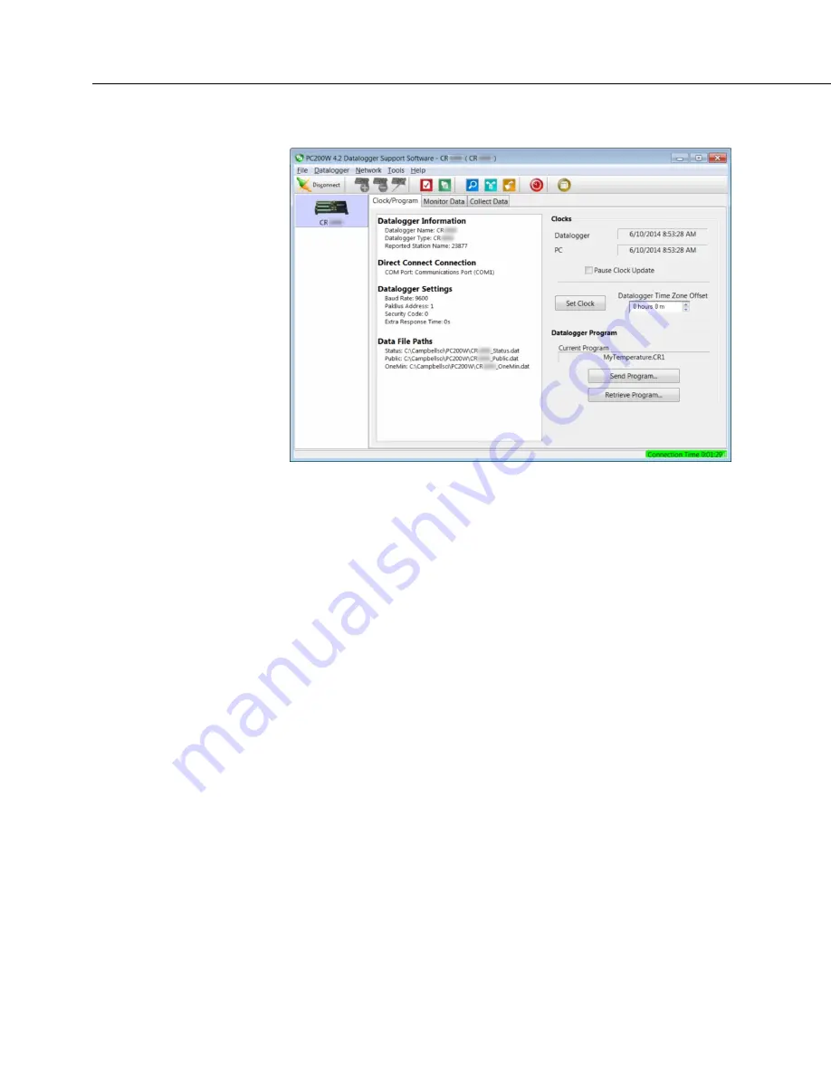
FIGURE 7: PC200W Main Window
4.6.5.2 Procedure: (PC200W Steps 2 to 4)
2. Click
Set Clock
(right pane, center) to synchronize the CR6 clock with the
computer clock.
3. Click
Send Program...
(right pane, bottom). A warning appears that data on
the datalogger will be erased. Click
Yes
. A dialog box will open. Browse
to the
C:\CampbellSci\SCWin
folder. Select the
MyTemperature.CR6
file.
Click
Open
. A status bar will appear while the program is sent to the CR6
followed by a confirmation that the transfer was successful. Click
OK
to
close the confirmation.
4. After sending a program to the CR6, a good practice is to monitor the
measurements to ensure they are reasonable. Select the
Monitor Data
tab. As
shown in the following figure,
PC200W
now displays data found in the CR6
Public
table.
Summary of Contents for CR6 Series
Page 2: ......
Page 4: ......
Page 6: ......
Page 32: ......
Page 36: ......
Page 38: ......
Page 76: ...Section 5 Overview 76 FIGURE 20 Half Bridge Wiring Example Wind Vane Potentiometer ...
Page 80: ...Section 5 Overview 80 FIGURE 23 Pulse Input Wiring Example Anemometer ...
Page 136: ......
Page 454: ...Section 8 Operation 454 FIGURE 104 Narrow Sweep High Noise ...
Page 459: ...Section 8 Operation 459 FIGURE 106 Vibrating Wire Sensor Calibration Report ...
Page 535: ...Section 8 Operation 535 8 11 2 Data Display FIGURE 121 CR1000KD Displaying Data ...
Page 537: ...Section 8 Operation 537 FIGURE 123 CR1000KD Real Time Custom ...
Page 538: ...Section 8 Operation 538 8 11 2 3 Final Storage Data FIGURE 124 CR1000KD Final Storage Data ...
Page 539: ...Section 8 Operation 539 8 11 3 Run Stop Program FIGURE 125 CR1000KD Run Stop Program ...
Page 541: ...Section 8 Operation 541 FIGURE 127 CR1000KD File Edit ...
Page 546: ......
Page 552: ......
Page 610: ...Section 11 Glossary 610 FIGURE 137 Relationships of Accuracy Precision and Resolution ...
Page 612: ......
Page 648: ......
Page 650: ......
Page 688: ......
Page 689: ......


