Cabletron Systems DLM6C-AA User Manual Download Page 68

Chapter 5: Local Management

5-6

DLEHF-MA User’s Guide

3.

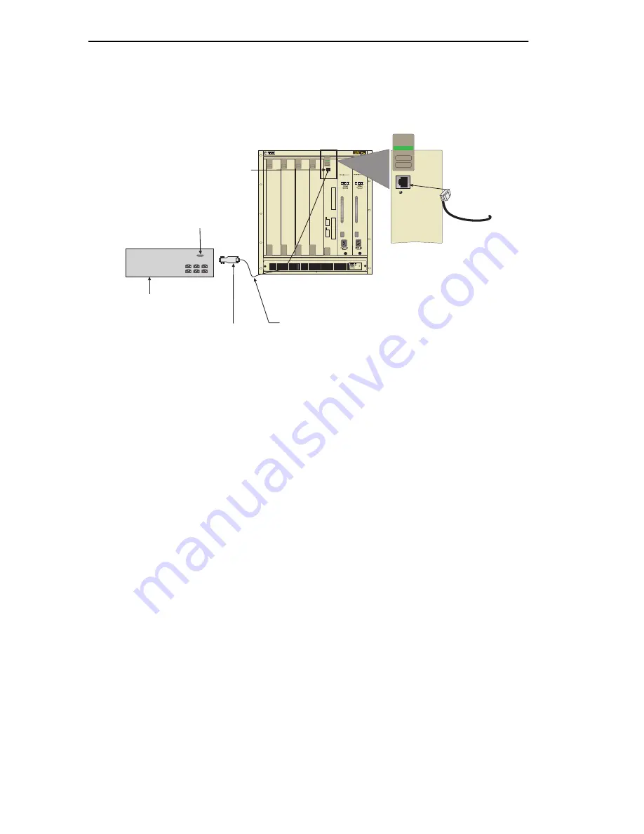
Connect the RJ45-to-DB9 male (UPS) adapter to the female DB9 port 
on the rear of the UPS device (refer to the particular UPS device’s user 
instructions for more specific information about the monitoring 
connection).

Figure 5-2

Uninterruptible Power Supply (UPS)

RJ45 COM Port

RJ45-to-DB9
UPS Adapter

UPS Device

DB9 Port

UTP Cable

With RJ45 Connectors

236208

1

2

3

4

5

PS1

PS2

1

2

COM

DLEHF-MA

Ethernet

CPU

COM

DLEHF-MA

Ethernet

CPU

TM

TM

TM

TM

Summary of Contents for DLM6C-AA

Page 1: ...DIGITAL MultiSwitch 700MD DLEHF MA Interface Module User s Guide ...

Page 2: ......

Page 3: ...User s Guide Part Number 9032624 October 1998 This manual describes the MultiSwitch 700MD Interface Module and provides information concerning installation troubleshooting and the use of Local Management Revision Update Information This is a new document ...

Page 4: ...ron Systems Inc DIGITAL and the DIGITAL logo are trademarks of Digital Equipment Corporation All other product names mentioned in this manual may be trademarks or registered trademarks of their respective companies UNITED STATES GOVERNMENT RESTRICTED RIGHTS The enclosed product a was developed solely at private expense b contains restricted computer software submitted with restricted rights in acc...

Page 5: ...Interference Regulations of the Canadian Department of Communications Le présent appareil numérique n émet pas de bruits radioélectriques dépassant les limites applicables aux appareils numériques de la class A prescrites dans le Règlement sur le brouillage radioélectrique édicté par le ministère des Communications du Canada VCCI Notice Class A Computing Device Taiwanese Notice Class A Computing D...

Page 6: ...nterpreted and governed under the laws and in the state and federal courts of New Hampshire You accept the personal jurisdiction and venue of the New Hampshire courts EXCLUSION OF WARRANTY AND DISCLAIMER OF LIABILITY 1 EXCLUSION OF WARRANTY Except as may be specifically provided by Cabletron in writing Cabletron makes no warranty expressed or implied concerning the Program including its documentat...

Page 7: ...nical Standardization When operating within their performance limitations laser transceiver output meets the Class 1 accessible emission limit of all three standards Class 1 levels of laser radiation are not considered hazardous SAFETY INFORMATION CLASS 1 LASER TRANSCEIVERS LASER RADIATION AND CONNECTORS When the connector is in place all laser radiation remains within the fiber The maximum amount...

Page 8: ...N 60950 Equipment Type Environment Networking Equipment for use in a Commercial or Light Industrial Environment We the undersigned hereby declare under our sole responsibility that the equipment packaged with this notice conforms to the above directives Manufacturer Legal Representative in Europe Mr Ronald Fotino Mr J Solari ___________________________________ ___________________________________ F...

Page 9: ...uto Negotiation 1 3 1 1 4 Management 1 3 1 1 5 Switching Options 1 4 1 1 6 Standards Compatibility 1 4 1 1 7 Year 2000 Compliance 1 4 1 1 8 LANVIEW Diagnostic LEDs 1 5 1 1 9 Runtime IP Address Discovery 1 5 1 2 Local Management Features 1 5 1 2 1 Distributed Chassis Management 1 5 1 2 2 Remote Monitoring RMON 1 6 1 2 3 Broadcast Suppression 1 6 1 2 4 Port Redirect Function 1 6 1 2 5 SmartTrunk 1 6...

Page 10: ...Overview 5 1 5 2 Local Management Keyboard Conventions 5 2 5 3 Management Terminal Setup 5 3 5 3 1 Console Cable Connection 5 3 5 3 2 Management Terminal Setup Parameters 5 4 5 3 3 Telnet Connections 5 5 5 3 4 Connecting an Uninterruptible Power Supply 5 5 5 4 Accessing Local Management 5 7 5 4 1 Navigating Local Management Screens 5 8 5 4 2 Selecting Local Management Menu Screen Items 5 10 5 4 3 ...

Page 11: ... Module Time 5 46 5 15 7 Entering a New Screen Refresh Time 5 47 5 15 8 Setting the Screen Lockout Time 5 47 5 15 9 Setting the Operational Mode 5 48 5 15 10 Setting the Management Mode 5 49 5 15 11 Configuring the COM Port 5 49 5 15 11 1 Changing the Com Port Application 5 51 5 15 12 Clearing NVRAM 5 53 5 15 13 Enabling Disabling IP Fragmentation 5 54 5 16 SNMP Community Names Screen 5 54 5 16 1 ...

Page 12: ...ies 5 84 5 25 2 Changing Source and Destination Ports 5 84 5 26 Broadcast Suppression Screen 5 85 5 26 1 Setting the Threshold 5 87 5 26 2 Resetting the Peak Rate 5 87 5 27 Module Statistics Menu Screen 5 87 5 28 Switch Statistics Screen 5 89 5 28 1 Using the Clear Counters Command 5 91 5 29 The Interface Statistics Screen 5 91 5 29 1 Displaying Interface Statistics 5 95 5 29 2 Using the Clear Cou...

Page 13: ... AND DELF3 UI SPECIFICATIONS B 1 DELTX UI B 1 B 2 DELFX UI B 2 B 3 DELF3 UI B 3 APPENDIX C OPTIONAL INSTALLATIONS AND MODE SWITCH BANK SETTINGS C 1 Required Tools C 1 C 2 Setting the Mode Switch C 1 C 3 Installing Optional Fast Ethernet Interface Modules C 4 INDEX ...

Page 14: ......

Page 15: ... Installation provides instructions on how to install the module in the chassis and connect segments to the device Chapter 4 Troubleshooting details the DLEHF MA LANVIEW LEDs that enable you to quickly diagnose network operational problems Chapter 5 Local Management describes how to access Local Management and use of the Local Management screens to manage the DLEHF MA interface module and the DLM6...

Page 16: ... DIGITAL FDDI Modular Media Interface DELHF UA User s Guide DIGITAL WAN Modular Interface DELHW UA User s Guide DIGITAL MultiSwitch 700 DLM6C AA Overview and Setup Guide DIGITAL Port Based VLAN User s Guide DIGITAL OPEN DECconnect Applications Guide or Cabletron Cabling Guide Note symbol Calls the reader s attention to any item of information that may be of special importance Caution symbol Contai...

Page 17: ...ing have the following information ready A description of the failure A description of any action s already taken to resolve the problem e g changing mode switches rebooting the unit etc A description of your network environment layout cable type etc Network load and frame size at the time of trouble if known The device history i e have you returned the device before is this a recurring problem et...

Page 18: ......

Page 19: ...nnten DANGER Déconseille à l utilisateur d exécuter une action pouvant entraîner des dommages matériels corporels voire même la mort AVISO Previene contra una acción que podría dañar el equipo provocar daños personales o la muerte CAUTION Contains information essential to avoid damage to the equipment ACHTUNG Liefert wichtige Informationen um einen Geräteschaden zu vermeiden ATTENTION Informations...

Page 20: ...onnel qualifié AVISO Sólo el personal cualificado debe instalar o dar mantenimiento a esta unidad WARNING The DELF3 UI uses Class 1 lasers Do not use optical instruments to view the laser output The use of optical instruments to view laser output increases eye hazard When viewing the output optical port power must be removed from the network adapter VORSICHT Einige DELF3 UI benutzen Laser der Klas...

Page 21: ...le are sensitive to static discharges Use an antistatic wrist strap and observe all static precautions during this procedure Failure to do so could damage the Fast Ethernet Interface Module or the host ACHTUNG Das DLEHF MA und das Hostsystemmodul sind für statische Entladungen empfindlich Benutzen Sie deshalb ein Antistatikarmband und beachten Sie während dieses Verfahrens alle diesbezüglichen Vor...

Page 22: ... ACHTUNG Eine Nichtbeachtung der Sicherheitsmaßnahmen hinsichtlich statischer Entladungen könnte Schäden am DLEHF MA verursachen Folgen Sie deshalb den Sicherheitsrichtlinien und tragen Sie das mit dem DLM6C AA Gehäuse gelieferte Antistatikarmband Benutzen Sie zum Öffnen der nicht leitfähigen Plastikhülle in dem sich das Modul befindet keine scharfen Instrumente da die Karte oder die Komponenten b...

Page 23: ...t nicht zu beschädigen stellen Sie sicher daß das Modul gerade eingeschoben und vorsichtig eingesetzt wird ATTENTION Pour éviter d endommager les connecteurs du backplane lors de l étape suivante veillez à ce que le module glisse tout droit et s adapte correctement aux connecteurs du backplane PRECAUCIÓN Para evitar dañar los conectores del plano posterior en el paso siguiente verifique que el mód...

Page 24: ...mpon de nettoyage de port optique imbibé d alcool isopropylique peut également être utilisé PRECAUCIÓN No toque los extremos de los filamentos de la fibra óptica ni permita que dichos extremos entren en contacto con polvo suciedad u otros contaminantes La contaminación de los extremos origina problemas en la transmisión de los datos Si los extremos se contaminan limpie su superficie con un plumero...

Page 25: ...ration section before changing the settings of the COM port ACHTUNG Bevor Sie die Einstellungen des COM Ports ändern stellen Sie sicher daß für das Modul oder das Gehäuse eine gültige IP Adresse eingestellt ist Lesen Sie den gesamten Abschnitt zur COM Port Konfiguration bevor Sie die Einstellungen des COM Ports ändern ATTENTION Avant de modifier les paramètres du port COM assurez vous qu une adres...

Page 26: ...In Standalone management mode the module does not use the community names of the DLM6C AA chassis ACHTUNG Bevor Sie den Betriebsmodus einstellen müssen Sie diese Vorsichtshinweise vollständig verstanden haben Der Management Modus des Moduls wird automatisch auf STAND ALONE gesetzt Das Feld Management Modus wird nicht mehr auf dem Bildschirm General Configuration Allgemeine Konfiguration angezeigt ...

Page 27: ...tonome Standalone le module n utilise pas les noms de communauté du châssis DLM6C AA PRECAUCIÓN Antes de definir el modo de funcionamiento asegúrese de haber comprendido plenamente todos los puntos de esta nota de precaución El modo de gestión Management Mode del módulo se definirá automáticamente como autónomo STAND ALONE El campo Management Mode ya no aparecerá en la pantalla de configuración ge...

Page 28: ...nal vom Port und beendet die LM Sitzung Wenn dem DLEHF MA zuvor eine gültige IP Adresse zugewiesen wurde gehen Sie wieder zu LM indem Sie eine Telnet Verbindung zum Gerät herstellen Wenn das Gerät keine gültige IP Adresse hat und der COM Port abgeschaltet wurde oder wenn die Einstellungen geändert wurden führen Sie einen NVRAM Reset auf dem DLEHF MA durch siehe Anhang C um die COM Port Kommunikati...

Page 29: ...ess set on the module or chassis the message shown in Figure 5 19 displays Do not continue unless you fully understand the outcome of this action If the Warning screen displays continue on to step 4 otherwise proceed to step 5 ACHTUNG Wenn der COM Port rekonfiguriert wird ohne daß auf dem Modul oder dem Gehäuse eine gültige IP Adresse eingestellt ist wird die in Abbildung 5 19 gezeigte Meldung ang...

Page 30: ...ez sur SAVE pour conserver les modifications s affiche Toutes vos modifications seront perdues PRECAUCIÓN Si sale sin guardar aparecerá el mensaje NOT SAVED PRESS SAVE TO KEEP CHANGES NO SE HA GUARDADO PULSE GUARDAR PARA CONSERVAR LOS CAMBIOS Si sale sin guardar se perderán todos los cambios CAUTION When the COM port is configured to perform the UPS application all future Local Management connecti...

Page 31: ...esse IP valable avant d enregistrer les modifications apportées au port COM Si le module n est pas doté d une adresse IP valable et que les modifications sont enregistrées reportez vous à l Annexe C pour apprendre comment initialiser la NVRAM avant de rétablir des communications COM PRECAUCIÓN Cuando el puerto COM está configurado para la aplicación UPS todas las conexiones de gestión local LM Loc...

Page 32: ...led all FDDI frames that exceed the maximum Ethernet frame size will be discarded ACHTUNG Wenn DLEHF MA per Bridge an einen FDDI Ring angeschlossen werden sollte IP Fragmentierung aktiviert werden Wenn IP Fragmentierung deaktiviert wird werden alle FDDI Frames die die maximale Ethernet Frame Größe überschreiten verworfen ATTENTION Si les appareils DLEHF MA sont reliés pontage sur un anneau FDDI la...

Page 33: ... der Gummistöpsel vom SC Anschlußstecker entfernt werden ATTENTION Lorsque vous installez un module DELFX UI ou un module DELF3 UI retirez la prise en caoutchouc placée sur le connecteur SC avant de procéder à l installation PRECAUCIÓN Al instalar un módulo DELFX UI o DELF3 UI en el módulo de host retire el enchufe de caucho del conector SC antes de continuar CAUTION When inserting the Fast Ethern...

Page 34: ...e assurez vous que les broches ne sont pas pliées car vous risquez d endommager à la fois le module et le connecteur PRECAUCIÓN Al insertar Fast Ethernet Interface Module en el conector de la placa base asegúrese de que las patillas no se doblen ya que esto podría dañar tanto Fast Ethernet Interface Module como el conector de la placa base ...

Page 35: ...idging and IEEE 802 1Q switching Ports 1 and 2 of the DLEHF MA support optional Fast Ethernet Interface Modules and can provide uplinks to 100BASE TX or 100BASE FX Fast Ethernet networks The DLEHF MA is capable of being equipped with two High Speed Interface Modules HSIMs that provide for additional connectivity to other high speed networking technologies such as Asynchronous Transfer Mode ATM Wid...

Page 36: ... DLEHF MA User s Guide Figure 1 1 The DLEHF MA COM DLEHF MA Ethernet System LED COM Port HSIM Slots 236201 Port Status LEDs CPU 1 2 Fast Ethernet Interface Module Ports 1 and 2 H S I M 1 H S I M 2 Reset Button RESET MultiSwitch ...

Page 37: ...wo devices automatically exchange information telling each other what their operating capabilities are The Auto Negotiation feature targets the maximum capabilities that can be reached between the two devices For example a DLEHF MA DELTX UI Fast Ethernet Interface Module adjusts to 100 Mbps when the device on the other end of the connection can also adjust between 10 or 100 Mbps If the device on t...

Page 38: ... replacement of existing equipment 1 1 6 Standards Compatibility The DLEHF MA is fully compliant with the IEEE 802 3 standard The optional Fast Ethernet Interface Modules are fully compliant with the IEEE 802 3u standard The DLEHF MA provides IEEE 802 1D Spanning Tree Algorithm STA support to enhance the overall reliability of the network and protect against loop conditions It also supports a wide...

Page 39: ...n IP address from a BootP or RARP server on the network The RAD requests start out at an interval of 1 second and double after every transmission until an interval of 300 seconds is reached At this point the interval remains at 300 seconds The RAD requests continue until an IP address is received from a BootP or RARP server or an IP address is entered using Local Management 1 2 LOCAL MANAGEMENT FE...

Page 40: ... Any broadcast frames above this specified limit are dropped In the event that broadcast frames are being suppressed multicast and unicast frames continue to be switched 1 2 4 Port Redirect Function The port redirect function also referred to as Port Mirroring is a troubleshooting tool used to map traffic from a single source port or multiple source ports to a destination port s within the chassis...

Page 41: ...ve SNMP traps from the DLEHF MA module and DLM6C AA chassis Configure module specific SNMP MIB objects including the IETF Bridge MIB objects Chapter 5 provides detailed information about Local Management of the DLEHF MA the optional Fast Ethernet Interface Modules and the DLM6C AA chassis The associated High Speed Interface Module user s guide provides detailed information about Local Management o...

Page 42: ... the Release Notes Table 1 1 Fast Ethernet Interface Modules P N Description Application DELTX UI Uses RJ45 connector Supports Category 5 Unshielded Twisted Pair UTP cabling with an impedance between 85 and 111 ohms DELFX UI Uses SC connector Supports multimode fiber optic cabling DELF3 UI Uses SC connector Supports single mode fiber optic cabling Other Fast Ethernet Interface Modules may be avail...

Page 43: ...onfiguration rules 2 2 100BASE TX NETWORK The DLEHF MA with a DELTX UI installed in ports 1 or 2 provides an RJ45 connection that supports Category 5 UTP cabling The device at the other end of the twisted pair segment must support IEEE 802 3u 100BASE TX Fast Ethernet operations The cabling between the devices must meet the test criteria for a 100BASE TX link for the devices to operate at 100 Mbps ...

Page 44: ...t 100 Mbps Refer to the Cabletron Cabling Guide or DIGITAL OPEN DECconnect Applications Guide for details Multimode Mode Fiber Optic Cable The test characteristics of a 100BASE FX segment are covered in the Cabletron Cabling Guide or DIGITAL OPEN DECconnect Applications Guide Single Mode Fiber Cable The test characteristics of a single mode fiber optic link are similar to those for a multimode fib...

Page 45: ... is required to install the Fast Ethernet Interface Modules in the DLEHF MA 3 2 UNPACKING THE DLEHF MA 1 Open the box and remove the packing material protecting the module do not remove the module from its non conductive bag 2 Verify the contents of the carton as listed in Table 3 1 Only qualified personnel should install or service this unit Table 3 1 Contents of DLEHF MA Carton Item Quantity DLE...

Page 46: ... cooling Save the blank plate in the event you need to remove the module 2 Carefully remove the module from the shipping box Save the box and packing materials in the event the module must be reshipped 3 Locate the antistatic wrist strap shipped with the DLM6C AA chassis Attach the antistatic wrist strap to your wrist and plug the cable from the antistatic wrist strap into the ESD grounding recept...

Page 47: ...le will be installed Install the module in the chassis by aligning the module circuit card between the upper and lower metal rail guides of the desired slot sliding it into the chassis and locking down the top and bottom plastic locking tabs as shown in Figure 3 1 To prevent damaging the backplane connectors in the following step take care that the module slides in straight and properly engages th...

Page 48: ... User s Guide Figure 3 1 Installing an Interface Module 1 2 3 4 5 PS1 PS2 Plastic Locking Tab Plastic Locking Tab Slot Number Circuit Card Card Guides Metal Back Panel 236202 COM DLEHF MA Ethernet CPU H S I M 2 H S I M 1 2 1 TM TM TM TM ...

Page 49: ... DELTX UI A DELTX UI installed in port 1 and or 2 has an internal crossover switch If you need a crossover set the Fast Ethernet Interface Module crossover switch shown in Figure 3 2 to the crossed over position marked with an X If you do not need a crossover set the Fast Ethernet Interface Module crossover switch shown in Figure 3 2 to the not crossed over position marked with an If the DLEHF MA ...

Page 50: ...m the following steps until it is on a Verify that the 100BASE TX device at the other end of the twisted pair segment is powered up b Verify that the RJ45 connector on the twisted pair segment has the proper pinouts c Check the cable for continuity d Make sure that the twisted pair connection meets dB loss and cable specifications outlined in the Cabletron Cabling Guide or DIGITAL OPEN DECconnect ...

Page 51: ... receive port of the other device and vice versa If the fiber optic cable being used has SC style connectors that do not resemble MIC style connectors or has SC connectors on one end and a different type on the other such as ST connectors ensure that the proper crossing over occurs The DELF3 UI uses Class 1 lasers Do not use optical instruments to view the laser output The use of optical instrumen...

Page 52: ... that the power is turned on for the device at the other end of the fiber optic cable b Verify proper crossing over of fiber strands between the applicable port on the DLEHF MA and the fiber optic device at the other end of the fiber optic cable c Verify that the fiber connection meets the dB loss specifications outlined in the Cabletron Cabling Guide or the DIGITAL OPEN DECconnect Applications Gu...

Page 53: ...ting the Installation DLEHF MA User s Guide 3 9 3 6 COMPLETING THE INSTALLATION The DLEHF MA is now ready to be set up through Local Management Refer to Chapter 5 to configure the module and DLM6C AA chassis ...

Page 54: ......

Page 55: ...lt in visual diagnostic and status monitoring system called LANVIEW The LANVIEW LEDs Figure 4 1 allow quick observation of the network status to aid in the diagnosing of network problems Refer to Table 4 1 for a description of the LEDs For a functional description of the LANVIEW LED on the optional Fast Ethernet Interface Module DELTX UI refer to Section 4 2 All LEDs for the High Speed Interface M...

Page 56: ...Chapter 4 Troubleshooting 4 2 DLEHF MA User s Guide Figure 4 1 LANVIEW LEDs 231104 COM DLEHF MA Ethernet System LED CPU 1 2 H S I M 1 H S I M 2 Receive RX Transmit TX RESET MultiSwitch ...

Page 57: ...r up chassis Red Blinking Hardware failure has occurred Contact your DIGITAL representative Solid Resetting normal power up reset None Amber Blinking Crippled Contact your DIGITAL representative Solid Testing None Green Solid Functional None Amber and Green Booting Blinks amber and green while booting None RX Off No link No activity Port enabled or disabled None Green Solid Port enabled link no ac...

Page 58: ...e 4 2 DELTX UI LED TX Off Port enabled and no activity 1 Ensure that the STA is enabled and that there is valid link 2 Contact your DIGITAL representative Green Flashing Indicates activity Rate indicates data rate None Amber Blinking Port in standby link 1 Ensure that the port is not disabled 2 Contact your DIGITAL representative for assistance Red Flashing Indicates collision rate None unless a h...

Page 59: ...he RX LED Is On LED Color Description 10 100 Off DELTX UI is operating at 10 Mbps Green DELTX UI is operating at 100 Mbps No link exists if the associated port port 1 or 2 Receive RX LED is off LED Color Description 10 100 Off No link or no cable attached DELTX UI forced to 10 Mbps operation or is manually set to auto negotiate mode Green No link or no cable attached DELTX UI is forced to 100 Mbps...

Page 60: ...proper console port pinouts Cannot contact the DLEHF MA from in band management Improper Community Names Table Refer to Chapter 5 for Community Names Table setup The DLEHF MA does not have an IP address Refer to Chapter 5 for IP address assignment procedure Port is disabled Enable port No link to device Check link to device Port s goes into standby for no apparent reason The DLEHF MA detects a loo...

Page 61: ...ecting the NVRAM Figure 4 3 RESET Button To reset the DLEHF MA processor use a pen or pencil to press and release the RESET button The DLEHF MA goes through the reset process and then reenters the network Pressing the RESET button resets the device and all current switching being performed by the device halts The device will be unavailable for up to two minutes during the reset process RESET DLEHF...

Page 62: ......

Page 63: ...tmaskstotheDLEHF MA andassignan IP address to the DLM6C AA chassis Control access to the DLEHF MA and the DLM6C AA chassis by establishing community names Download a new image of operating software Designate which Network Management Workstations receive SNMP traps from the DLEHF MA Monitor the environmental status of the DLM6C AA chassis View switch interface and RMON statistics Assign ports to op...

Page 64: ... you otherwise ESCAPE ESC Key This key allows an escape from a Local Management screen without saving changes For example Press ESC twice means the ESC key must be pressed quickly two times SPACE bar BACKSPACE Key These keys cycle through selections in some Local Management fields Use the SPACE bar to cycle forward through selections and use BACKSPACE to cycle backward through selections Arrow Key...

Page 65: ... Kit provided with the DLM6C AA chassis to attach the management terminal to the COM port as shown in Figure 5 1 Connect an IBM PC or compatible device running the VT terminal emulation to the DLEHF MA as follows 1 Connect the RJ45 connector at one end of the cable supplied in the kit to the COM port on the DLEHF MA 2 Plug the RJ45 connector at the other end of the cable into the RJ45 to DB9 adapt...

Page 66: ...line Cursor Style General Setup Menu Mode ID number Cursor Keys Power Supply VT100 7 Bit Controls VT100ID Normal Cursor Keys UPSS DEC Supplemental Communications Setup Menu Transmit Receive XOFF Bits Parity Stop Bit Local Echo Port Transmit Auto Answerback 2400 4800 9600 19200 Receive Transmit XOFF at 64 8 bits No Parity 1 Stop Bit No Local Echo DEC 423 Data Leads Only Limited Transmit No Auto Ans...

Page 67: ...e DLEHF MA is connected to an American Power Conversion APC Uninterruptible Power Supply UPS device for power a connection from its COM port to the UPS allows monitoring of the UPS power status The COM port must first be reconfigured to support the UPS connection using the General Configuration LM screen as described in Section 5 15 11 Refer to the UPS documentation for details on how to access th...

Page 68: ...ice refer to the particular UPS device s user instructions for more specific information about the monitoring connection Figure 5 2 Uninterruptible Power Supply UPS RJ45 COM Port RJ45 to DB9 UPS Adapter UPS Device DB9 Port UTP Cable With RJ45 Connectors 236208 1 2 3 4 5 PS1 PS2 1 2 COM DLEHF MA Ethernet CPU COM DLEHF MA Ethernet CPU TM TM TM TM ...

Page 69: ...reviously stored passwords The level of access allowed the user depends on the password To set or change passwords refer to Section 5 8 The following steps describe the procedure to access Local Management 1 Turn on the terminal Press ENTER until the DLM6C AA Local Management Password screen this may take up to four times because the COM port auto senses the baud rate of the terminal Figure 5 3 di...

Page 70: ...ration The switching modes are as follows 802 1D SWITCHING IEEE 802 1D switching 802 1Q SWITCHING 802 1Q port based VLANs The switch operational mode may be set in either the Chassis Configuration screen Section 5 7 or the General Configuration screen of the module Section 5 15 Depending on the Operational Mode set for the module the hierarchy of Local Management screens differs as shown in Figure...

Page 71: ... High Speed Interface Configuration Flash Download Broadcast Suppression Fast Ethernet HSIM Module Statistics Menu Switch Statistics RMON Statistics Interface Statistics Network Tools 236210 Module Menu Password Main Menu SNMP Community Names Chassis Menu Chassis Configuration SNMP Traps Chassis Environmental Module Configuration Menu Module Specific Configuration General Configuration SNMP Commun...

Page 72: ...Press ENTER The Password screen displays and the session ends Using the RETURN Command To exit an LM screen using the RETURN command proceed as follows 1 Use the arrow keys to highlight the RETURN command at the bottom of the Local Management screen 2 Press ENTER The previous screen in the Local Management hierarchy displays 3 Exit from DLEHF MA Local Management by repeating steps 1 and 2 until th...

Page 73: ...s the accesspointfor allLocal Managementscreens for the module and the DLM6C AA chassis Figure 5 6 shows the Main Menu screen Figure 5 6 Main Menu Screen The following explains each Main Menu screen item as shown in Figure 5 6 Main Menu 236213 MS 700 LOCAL MANAGEMENT CHASSIS EXIT MODULES RETURN ...

Page 74: ... 6 MODULES The Modules menu item provides access to the Module Selection screen that is used to select individual modules in the chassis for management purposes To access the Module Selection screen use the arrow keys to highlight the MODULES menu item and press ENTER The Module Selection screen displays For details about the Module Selection screen refer to Section 5 12 5 6 CHASSIS MENU SCREEN Th...

Page 75: ... for the DLM6C AA chassis For details refer to Section 5 7 SNMP COMMUNITY NAMES The SNMP Community Names screen allows the user to enter new change or review the community names used as access passwords for device management operation Access is limited based on the password level of the user For details refer to Section 5 8 MS 700 LOCAL MANAGEMENT Chassis Menu CHASSIS CONFIGURATION 236214 RETURN S...

Page 76: ...t Redirect Function screen allows the user to redirect traffic from one or multiple modules and ports in the chassis to a specific destination module or port For details refer to Section 5 11 5 7 CHASSIS CONFIGURATION SCREEN The Chassis Configuration screen Figure 5 8 allows the user to set the chassis date and time IP address and Subnet Mask the operational mode of all modules installed in the ch...

Page 77: ...ys the subnet mask for the chassis A subnet mask masks out the network bits of the IP address by setting the bits in the mask to 1 when the network treats the corresponding bits in the IP address as part of the network or subnetwork address or to 0 if the corresponding bit identifies Some firmware versions do not support the changing of the chassis subnet mask from the default value Refer to the R...

Page 78: ... information isupdated on the screen To enter a new update time refer to Section 5 7 5 Screen Lockout Time Modifiable Contains the maximum number of minutes that the Local Management applicationdisplaysa module s screenwhile awaiting inputor action from a user For example if the number 5 is entered in this field the user has up to five minutes to respond to each of the specified module s Local Man...

Page 79: ...llowing steps 1 Use the arrow keys to highlight the IP Address field 2 Enter the IP address into this field using Decimal Dotted Notation DDN format For example 134 141 79 120 3 Press ENTER If the IP address is a valid format the cursor returns to the beginning of the IP address field If the entry is not valid the Event Message Line displays INVALID IP ADDRESS OR FORMAT ENTERED Local Management do...

Page 80: ...RED Local Management does not alter the current value but it does refresh the Subnet Mask field with the previous value 4 Use the arrow keys to highlight the SAVE command then press ENTER The changes are saved to memory 5 7 3 Setting the Chassis Date The DLM6C AA is year 2000 compliant so the Chassis Date may be set beyond the year 1999 To set the chassis date perform the following steps 1 Use the...

Page 81: ...time to the time in the input field 4 Use the arrowkeystohighlightthe SAVEcommandatthebottom ofthe screen and press ENTER If the time entered is a valid format the Event Message Line at the top of the screen displays SAVED OK If the entry is not valid Local Management does not alter the current value and refreshes the Chassis Time field with the previous value Upon saving the new chassis date all ...

Page 82: ...s not valid Local Management does not alter the current setting but it does refresh the Screen Refresh Time field with the previous value 5 7 6 Setting the Screen Lockout Time The screen lockout time can be set from 1 to 30 minutes with a default of 15 minutes To set a new lockout time perform the following steps 1 Use the arrow keys to highlight the Screen Lockout Time field 2 Enter a number from...

Page 83: ... SWITCHING all modules in the chassis will operate as traditional switches 3 Use the arrow keys to highlight the SAVE command at the bottom of the screen and press ENTER The warning screen shown in Figure 5 9 displays Figure 5 9 Operational Mode Warning Screen 4 Use the arrow keys to highlight the YES command and press ENTER The changes are saved and all the modules installed in the chassis reboot...

Page 84: ...read only read write and super user To access the SNMP Community Names screen from the Chassis Menu screen use the arrow keys to highlight the SNMP COMMUNITY NAMES menu item and press ENTER The SNMP Community Names screen Figure 5 10 displays If the DLEHF MA has been set to 802 1Q SWITCHING refer to the Port Based VLAN User s Guide to configure the device for this type of operation Super user acce...

Page 85: ...icatestheaccessaccordedeachcommunityname Possibleselectionsare as follows read only This community name allows read only access to the DLM6C AA MIB objects and excludes access to security protected fields of read write or super user authorization read write This community name allows read and write access to the DLM6C AA MIB objects excluding security protected fields for super user access only MS...

Page 86: ...ess level 2 Enter the password in the field maximum 31 characters 3 Press ENTER 4 Repeat steps 1 through 3 to modify the other community names 5 Use the arrow keys to highlight SAVE at the bottom of the screen and press ENTER The message SAVED OK displays The community names are saved to memory and their access modes implemented Any community name assigned in the SNMP Community Names screen is a p...

Page 87: ...e SNMP Traps screen displays Figure 5 11 Chassis SNMP Traps Screen The following explains each field of the SNMP Traps screen Trap Destination Modifiable Indicates the IP address of the workstation to receive trap alarms Up to eight different destinations can be defined Exiting without saving causes a NOT SAVED message to display above the SAVE command Edits will be lost if they are not saved befo...

Page 88: ...aps IP address entries must follow the DDN format For example 134 141 79 121 3 Press ENTER If an invalid entry is entered INVALID IP ENTERED is displayed in the Event Message Line 4 Using the arrow keys highlight the Trap Community Name field Enter the community name 5 Press ENTER 6 Using the arrow keys highlight the Enable Traps field Press the SPACE bar to choose either YES send alarms from the ...

Page 89: ...sis Environmental Information screen fields Chassis Power Redundancy Read Only Displays the current redundancy status of the DLM6C AA power supplies This field will read either Available or Not Available Power Supply X Status Read Only Displays the current status of power supplies 1 and 2 for the DLM6C AA This field will read either Normal Fault or Not Installed Chassis Fan Status Read Only Displa...

Page 90: ...mely useful for troubleshooting purposes as it allows traffic to be sent to a particular port s where with the use of an analyzer or RMON probe all current traffic from the source port s can be examined To access the Port Redirect Function screen from the Chassis Menu screen use the arrow keys to highlight the PORT REDIRECT menu item and press ENTER The Port Redirect Function screen Figure 5 13 di...

Page 91: ...estination ports Remap Errors Read Only Shows whether destination ports and modules are receiving errored frames and valid traffic ON or just valid traffic OFF Source Port n Selectable Allows a selected port n to be configured as a source port Port Redirect Function 236219 Module 3 3 3 1 3 4 5 5 Port 2 3 4 1 3 4 5 8 Errors ON Port 1 1 1 2 2 3 3 3 Module 1 1 1 2 2 3 3 3 Source Destination Remap Err...

Page 92: ...this field is ON For information on how to change the default setting refer to Section 5 11 2 5 11 1 Displaying the Source and Destination Entries There can be more than one Port Redirect Function screen depending on the number of port redirect entries Each screen displays up to ten port redirect entries If there is more than one screen of redirect entries the NEXT and or PREVIOUS command is displ...

Page 93: ... Destination Port field 8 Use the SPACE bar or BACKSPACE to step to the appropriate port number for the destination port 9 Use the arrow keys to highlight the Status field 10 Use the SPACE bar to toggle between the ADD and DEL delete settings Press ENTER This adds or deletes the port selections made in steps 2 and 4 and also updates the screen Source Port and Destination Port list 11 Use the arrow...

Page 94: ...LES menu item and press ENTER Figure 5 14 Module Selection Screen The following explains each Module Selection screen field as shown in Figure 5 14 Slot TheSlot fielddisplaystheslotinwhichthemoduleisinstalled Themodule number enclosed in characters indicates the module to which the management terminal is connected Module Name TheModuleNamefielddisplaysthetypeofinterfacemodulethatisinstalled in eac...

Page 95: ...our DIGITAL representative Hardware Revision Reflects the hardware version of the module 5 12 1 Selecting a Module To select an individual module to perform Local Management functions proceed as follows 1 Use the arrow keys to highlight the desired module number in the Slot field 2 Press ENTER the applicable Module Menu screen displays Proceed to Section 5 13 ...

Page 96: ...re used to configure the DLEHF MA and also provides access to the Module Specific Configuration Menu screen The Module Specific Configuration Menu screen provides access to the screens that allow the user to check the DLEHF MA resources and set operating parameters specific to each port For details about the Module Configuration Menu screen refer to Section 5 14 For details about the Module Specif...

Page 97: ...Management screens that allow you to configure and monitor operating parameters modify SNMP community names set SNMP traps configure switch parameters and configure the DLEHF MA ports To access the Module Configuration Menu screen from the Module Menu screen use the arrow keys to highlight the MODULE CONFIGURATION menu item and press ENTER The Module Configuration Menu screen displays The Switch C...

Page 98: ...e community names used as access passwords for Local Remote management operation Access is limited based onthe password level of the user For details refer to Section 5 16 SNMP TRAPS The SNMP Traps screen provides display and configuration access to the table of IP addresses used for trap destinations and associated community names For details refer to Section 5 17 MS 700 LOCAL MANAGEMENT Firmware...

Page 99: ...o Section 5 18 SMARTTRUNK CONFIGURATION The SmartTrunk Configuration screen allows the user to logically group interfaces together to create higher bandwidth uplinks For details refer to Section 5 19 MODULE SPECIFIC CONFIGURATION The Module Specific Configuration Menu screen allows the user to configure ports or check system resources specific to the DLEHF MA For details refer to Section 5 20 ...

Page 100: ...General Configuration Screen The following briefly explains each General Configuration screen field MAC Address Read Only Displays the physical address of the module IP Address Modifiable This display allows the IP address to be set for the DLEHF MA To set the IP address refer to Section 5 15 1 MS 700 LOCAL MANAGEMENT Firmware Revision XX XX XX General Configuration 236223 BOOTPROM Revision XX XX ...

Page 101: ...ule Date Modifiable Contains a value that the module recognizes as the current date To set a new module date refer to Section 5 15 5 Module Time Modifiable Contains a value that the module recognizes as the current time To enter a new time refer to Section 5 15 6 Screen Refresh Time Modifiable Contains the rate at which the screens are updated This setting determines how frequently in seconds info...

Page 102: ...to the user All other modules installed in the chassis that are set for distributed management may also be accessed via a connection to a single COM port on one of the modules The user can then manage all modules within the chassis and the chassis itself In STAND ALONE mode the module is isolated from the chassis configuration screens and the module may not be accessed from a module that is in DIS...

Page 103: ...is automatically sensed For details about how to configure the COM port for various applications refer to Section 5 15 11 Clear NVRAM Toggle This allows the user to reset NVRAM to the factory default settings All user entered parameters such as IP address and Community Names are then replaced with DLEHF MA default configuration settings For details refer to Section 5 15 12 IP Fragmentation Toggle ...

Page 104: ...INVALID IP ADDRESS OR FORMAT ENTERED Local Management does not alter the current value and refreshes the IP address field with the previous value 4 Use the arrow keys to highlight the SAVE command then press ENTER The warning screen shown in Figure 5 displays If the DLM6C AA chassis has been assigned an IP address it is not necessary to assign an IP address to the DLEHF MA All installed modules ha...

Page 105: ...change the subnet mask from its default perform the following steps 1 Use the arrow keys to highlight the Subnet Mask field 2 Enter the subnet mask into this field using Decimal Dotted Notation DDN format For example 255 255 255 0 3 Press ENTER If the subnet mask is valid the cursor returns to the beginning of the Subnet Mask field If the entry is not valid the Event Message Line displays INVALID ...

Page 106: ...fault Gateway field 2 Enter the IP address of the default gateway using the DDN format For example 134 141 79 121 3 Press ENTER If the default gateway entered is a valid format the cursor returns to the beginning of the Default Gateway field If the entry is not valid the Event Message Line displays INVALID DEFAULT GATEWAY OR FORMAT ENTERED Local Management does not alter the current value but it d...

Page 107: ...5 Press ENTER The Event Message Line at the top of the screen displays SAVED OK 5 15 5 Setting the Module Date The module is year 2000 compliant so the module date may be set beyond the year 1999 To set the module date perform the following steps 1 Use the arrow keys to highlight the Module Date field 2 Enter the date in this format MM DD YYYY 3 Press ENTER to set the module date to the date in th...

Page 108: ...the arrow keys to highlight the SAVE command at the bottom of the screen and press ENTER If the time entered is a valid format the Event Message Line at the top of the screen displays SAVED OK If the entry is not valid Local Management does not alter the current value and refreshes the Module Time field with the previous value If the DLM6C AA chassis has been assigned a chassis time it is not nece...

Page 109: ... 4 Use the arrow keys to highlight the SAVE command at the bottom of the screen and press ENTER If the time entered is within the 3 to 99 seconds range the Event Message Line at the top of the screen displays SAVED OK If the entry is not valid Local Management does not alter the current setting but it does refresh the Screen Refresh Time field with the previous value 5 15 8 Setting the Screen Lock...

Page 110: ... step to the appropriate operation mode 802 1D SWITCHING 802 1Q SWITCHING 3 Use the arrow keys to highlight the SAVE command at the bottom of the screen and press ENTER The warning screen shown back in Figure 5 displays 4 Use the arrow keys to highlight the YES command and press ENTER The changes are saved and the module reboots Before setting the operational mode ensure that the items contained i...

Page 111: ...w operational mode the module will reboot If the DLEHF MA has been set to 802 1Q SWITCHING refer to the Port Based VLAN User s Guide to configure the device for this type of operation Upon saving the new operational mode the module will reboot If the module will be set to STAND ALONE ensure the following procedures have been completed The module has been assigned a unique IP address that has been ...

Page 112: ...ing the current Local Management LM connection through a terminal Altering the COM port settings disconnects the LM terminal from the port and ends the LM session If the DLEHF MA was previously assigned a valid IP address reenter LM by establishing a Telnet connection to the device If the device does not have a valid IP address and the COM port has been disabled or the settings changed reset NVRAM...

Page 113: ...Port Application After enabling the COM port as described in Section 5 15 11 you can select one of the applications supported by the COM port LM or UPS The default application is LM To change the COM port application 1 Use the arrows keys to highlight the Application field Exiting without saving causes the message NOT SAVED PRESS SAVE TO KEEP CHANGES to display Exiting without saving causes all ed...

Page 114: ...SAVED OK displays the edits are saved Table 5 3 COM Port Application Settings Setting Application LM Local Management Session UPS APC Power Supply SNMP Proxy When the COM port is configured to perform the UPS application all future Local Management connections must be made by establishing a Telnet connection to the module Ensure that the module has a valid IP address before saving changes to the C...

Page 115: ...e 5 19 displays 5 Use the arrow keys to highlight YES and press ENTER The message CLEARING NVRAM REBOOT IN PROGRESS displays The DLEHF MA clears NVRAM and reboots All user entered parameters default to factory settings Figure 5 19 Clear NVRAM Warning Screen Clearing NVRAM will result in the loss of all user entered parameters Do not proceed unless you completely understand this procedure WARNING 2...

Page 116: ...y Names screen from the Module Configuration Menu screen use the arrow keys to highlight the SNMP COMMUNITY NAMES menu item and press ENTER The SNMP Community Names screen Figure 5 20 displays If the DLEHF MA is being bridged to an FDDI ring IP Fragmentation should be enabled If IP Fragmentation is disabled all FDDI frames that exceed the maximum Ethernet frame size will be discarded If the DLM6C ...

Page 117: ... Possible selections are as follows read only This community name allows read only access to the DLEHF MA MIB objects and excludes access to security protected fields of read write or super user authorization read write This community name allows read and write access to the DLEHF MA MIB objects excluding security protected fields for super user access only MS 700 LOCAL MANAGEMENT Firmware Revisio...

Page 118: ...as follows 1 Use the arrow keys to highlight the Community Name field adjacent to the selected access level 2 Enter the password in the field maximum 31 characters 3 Press ENTER 4 Repeat steps 1 through 3 to modify the other community names 5 Use the arrow keys to highlight SAVE at the bottom of the screen and press ENTER The message SAVED OK displays The community names are saved to memory and th...

Page 119: ... screen Trap Destination Modifiable Indicates the IP address of the workstation to receive trap alarms Up to eight different destinations can be defined It is only necessary to assign SNMP traps if the user desires the traps to be sent to different addresses than those assigned in Section 5 9 which details how to set SNMP traps for the DLM6C AA chassis MS 700 LOCAL MANAGEMENT Firmware Revision XX ...

Page 120: ...rkstation that is to receive traps IP address entries must follow the DDN format For example 134 141 79 121 3 Press ENTER If an invalid entry is entered INVALID IP ENTERED is displayed in the Event Message Line 4 Using the arrow keys highlight the Trap Community Name field Enter the community name 5 Press ENTER 6 Using the arrow keys highlight the Enable Traps field Press the SPACE bar to choose e...

Page 121: ... screen displays only if the operational mode of the chassis or the DLEHF MA has been set to 802 1D SWITCHING or 802 1Q SWITCHING Refer to Section 5 7 7 for instructions on configuring the chassis to operate in this mode and Section 5 15 9 for instructions on configuring the DLEHF MA to operate in this mode Ports 1 through 4 on the screen represent the optional Fast Ethernet Interface Modules and ...

Page 122: ...ts switch table before discarding it The modules will discard an address from their switch table if they do not receive a valid packet from the applicable address in the amount of time specified in the Age Time field To change the Age Time field from the default value of 300 seconds refer to Section 5 18 2 Firmware Revision XX XX XX Switch Configuration 236229 BOOTPROM Revision XX XX XX Port 1 2 3...

Page 123: ...om the learning to the forwarding state Forwarding The switch is on line and this interface is forwarding traffic Blocking This interface will not forward any traffic through the switch because a loop condition has been detected by the STA Status Toggle Allows the user to disable or enable a port by setting the status of the listed interface to either ENABLED or DISABLED To set the port status ref...

Page 124: ...ssage SAVED OK is displayed 5 18 3 Setting Enabling or Disabling the Port Status To set the status of an interface port proceed as follows 1 Use the arrow keys to highlight the Status field of the port 2 Use the SPACE bar to toggle to either ENABLED or DISABLED 3 Use the arrow keys to highlight the SAVE command at the bottom of the screen 4 Press ENTER The message SAVED OK is displayed Disabling t...

Page 125: ...3 A maximum of 12 ports may be used per instance and there may only be 8 instances per device 4 If three or more devices are connected together for SmartTrunking then the ports that connect any of the two devices together MUST be designated as USER ports to prevent a network loop condition The port with the least amount of bandwidth available would be the port s that should be designated a USER po...

Page 126: ...ports This is deemed an illegal configuration If a network loop exists when a port is disabled then SmartTrunk will reconfigure the remaining ports and continue to distribute traffic If a device has multiple instances to separate modules installed in the same chassis the results are unpredictable DIGITAL does not recommend implementing this type of configuration 5 19 2 SmartTrunk Configuration Scr...

Page 127: ...is field toggles between USER and NETWORK USER is not used for load sharing NETWORK is used for load sharing At least two ports must be designated as NETWORK to perform load sharing Interfaces with the Port Name Backplane and Host may display on this screen These ports may not be used for SmartTrunking Firmware Revision XX XX XX Smart Trunk Configuration Screen 236230 BOOTPROM Revision XX XX XX Mo...

Page 128: ...1 consists of 2 ST ports ports 1 and 2 5 19 3 Enabling the Connection To enable the Connection type proceed as follows 1 Use the arrow keys to highlight the Connection field for the selected port s 2 Press the SPACE bar to select USER or NETWORK 3 Use the arrows keys to highlight the ENABLE command at the bottom of the screen 4 Press ENTER The message SAVED OK is displayed 5 20 MODULE SPECIFIC CON...

Page 129: ...t Ethernet Interfaces screen and the HSIM screens For details refer to Section 5 22 The Broadcast Suppression menu item displays only if the operational mode of the chassis or the DLEHF MA has been set to 802 1D SWITCHING or 802 1Q SWITCHING Refer to Section 5 7 7 for instructions on configuring the chassis to operate in this mode and Section 5 15 9 for instructions on configuring the DLEHF MA to ...

Page 130: ...02 1Q VLAN CONFIGURATION This menu item will only display if the module has been configured to operate as an IEEE 802 1Q switch When selected this menu item opens the VLAN Main Menu screen For details refer to the DIGITAL MultiSwitch 700 Port Based VLAN User s Guide Section 5 15 9 describes how to configure the module to function as an 802 1Q switch 5 21 SYSTEM RESOURCES SCREEN The System Resource...

Page 131: ...lable DRAM Installed Read only Indicates the amount of DRAM installed in the DLEHF MA and how much of it is currently available Firmware Revision XX XX XX System Resources 236232 BOOTPROM Revision XX XX XX Flash Memory Installed 4 MB DRAM Installed 20 MB NVRAM Installed XX KB Available XXXXX Bytes CPU Type i960 HT 25Mhz Current Switch Utilization 66 Peak Switch Utilization 75 Reset Peak Switch Uti...

Page 132: ... Switch Utilization To reset the peak switch utilization to zero proceed as follows 1 Use the arrow keys to highlight the Reset Peak Switch Utilization field 2 Press the SPACE bar to select YES 3 Use the arrows keys to highlight the SAVE command at the bottom of the screen 4 Press ENTER The message SAVED OK is displayed 5 22 HIGH SPEED INTERFACE CONFIGURATION MENU SCREEN To access the High Speed I...

Page 133: ...ERFACES Displays the types of Fast Ethernet Interface Modules installed in ports 1 and 2 their current operating mode and indicates if the ports are linked This screen also allows the user to enable or disable Auto Negotiation and set the Advertised Ability HSIMS Displays the types of interfaces installed in the High Speed Interface Module HSIM slots The HSIM screens are depicted in their associat...

Page 134: ...ent operating mode and indicates if the ports are linked This screen also allows the user to enable or disable Auto Negotiation and set the Advertised Ability To access the High Speed Interface Configuration screen from the High Speed Interface Configuration Menu screen use the arrow keys to highlight the FAST ETHERNET INTERFACES menu item and press ENTER The High Speed Interface Configuration scr...

Page 135: ...re is a physical connection from this port to another 10BASE T or 100BASE TX FX device One of the following values is displayed Link There is a link signal present and a valid physical connection to another 10BASE T or 100BASE TX FX device No Link There is no link signal present and there is no valid physical connection to another device MS 700 LOCAL MANAGEMENT Firmware Revision XX XX XX High Spee...

Page 136: ...able of auto negotiating the operational mode and no further user setup is required Section 5 23 3 describes how to configure a DELTX UI Advertised Ability Selectable During auto negotiation the DELTX UI tells the device at the other end of the segment what its capabilities are The capabilities of a port 1 or 2 with a DELTX UI installed are 10BASE T 10BASE TFD full duplex mode 100BASE TX and 100BA...

Page 137: ...ll duplex 3 Press ENTER The port now operates in the chosen mode 4 Use the arrow keys to highlight the SAVE command Press ENTER The message SAVED OK displays and Local Management saves the changes to memory 5 23 3 Configuring a DELTX UI in Port 1 or 2 In normal operation a port 1 or 2 with a DELTX UI interface automatically establishes a link with the device at the other end of the segment and no ...

Page 138: ...le modes and not operate in other modes This field steps between 10Base T 10Base TFD full duplex 100Base TX and 100Base TXFD full duplex To set the advertised ability proceed as follows 1 Use the arrow keys to highlight the Advertised Ability field 2 Use the SPACE bar to select the desired mode 3 Use the RIGHT ARROW key to move across to the Enabled Disabled field to the right of the selection 4 U...

Page 139: ...to the specific workstation documentation Boot PROM downloads hex cannot be done through HSIM ports If downloading through an HSIM runtime download must be used Firmware based downloads fls can be done through any port Download Server IP and Download File Name are displayed only when TFTP or RUNTIME are selected in Download Method MS 700 LOCAL MANAGEMENT Firmware Revision XX XX XX Flash Download D...

Page 140: ...ut a BootP request to determine the IP address of the TFTP server and the filename of the image to be downloaded If set for TFTP or RUNTIME the DLEHF MA attempts a TFTP download based on the IP address and filename entered in the fields at the bottom of the Flash Download screen Section 5 24 1 describes how to download using TFTP Section 5 24 2 describes how to download using RUNTIME Section 5 24 ...

Page 141: ... the IP address of the TFTP gateway defined in the General Configuration screen in Section 5 15 4 Last Image Server IP Read only This field shows the IP address of the server used for the previous FLASH Download Last Image File Name Read only This field shows the complete path and file name of the last image downloaded to FLASH If TFTP or RUNTIME is selected as the download method Figure 5 28 the ...

Page 142: ...oot 6M146 hex 9 Use the arrow keys to highlight EXECUTE at the bottom of the screen and press ENTER The message TFTP DOWNLOAD WILL COMMIT TO FLASH REBOOT IN PROGRESS displays in the event message line at the top of the screen and the new image is downloaded into FLASH memory 5 24 2 Image File Download Using RUNTIME Set the DLEHF MA to download to FLASH using RUNTIME as follows 1 Use the arrow keys...

Page 143: ...ad server For example tftpboot 6M146 fls 11 Use the arrow keys to highlight EXECUTE at the bottom of the screen and press ENTER The message RUNTIME DOWNLOAD WILL COMMIT TO FLASH displays in the event message line at the top of the screen and the new image is downloaded into FLASH memory 5 24 3 Image File Download Using BootP Set the DLEHF MA to download to FLASH using BootP as follows 1 Use the ar...

Page 144: ...also serve as a destination port for other ports The port redirect function is extremely useful for troubleshooting purposes as it allows traffic to be sent to a particular port s where with the use of an analyzer or RMON probe all current traffic from the source port s can be examined To access the Port Redirect Function screen from the Module Specific Configuration screen use the arrow keys to h...

Page 145: ... destination ports are receiving errored frames and valid traffic ON or just valid traffic OFF Source Port n Selectable Allows a selected port n to be changed to a source port Destination Port n Selectable Allows a selected port n to be changed to a destination port Firmware Revision XX XX XX Port Redirect Function 236236 BOOTPROM Revision XX XX XX Source Port 2 3 4 Destination Port 1 1 1 Module T...

Page 146: ...t entries Each screen displays up to 10 port redirect entries If there is more than one screen of redirect entries the NEXT and or PREVIOUS command is displayed at the bottom of the screen allowing the user to navigate to either the next or previous screen 5 25 2 Changing Source and Destination Ports Add or delete source port and destination port entries as follows 1 Use the arrow keys to highligh...

Page 147: ...bottom of the screen Press ENTER The message SAVED OK is displayed This saves the new settings and updates the Source Port and Destination Port read only fields 5 26 BROADCAST SUPPRESSION SCREEN The Broadcast Suppression screen Figure 5 30 allows the user to set a desired limit of receive broadcast frames per port per second Any broadcast frames received above the desired threshold during the one ...

Page 148: ...eived Peak Rate Read Only Displays the number of broadcast frames received per second Time Since Peak Read Only Displays the time since peak broadcast frames received Threshold Modifiable Allows the user to set the desired limit of receive broadcast frames that will be forwarded per port per second Firmware Revision XX XX XX Broadcast Suppression 236237 BOOTPROM Revision XX XX XX Port 1 2 3 4 Time...

Page 149: ... To reset the Peak Rate field to zero proceed as follows 1 Use the arrow keys to highlight the Reset Peak field for the selected port 2 Press the SPACE bar to select YES 3 Use the arrows keys to highlight the SAVE command at the bottom of the screen 4 Press ENTER The message SAVED OK is displayed 5 27 MODULE STATISTICS MENU SCREEN The Module Statistics Menu screen Figure 5 31 provides access to sc...

Page 150: ...tched interface on an interface by interface basis For details refer to Section 5 29 The Switch Statistics menu item displays only if the operational mode of the chassis or the DLEHF MA has been set to 802 1D SWITCHING or 802 1Q SWITCHING Refer to Section 5 7 7 for instructions on configuring the chassis to operate in this mode and Section 5 15 9 for instructions on configuring the DLEHF MA to ope...

Page 151: ... the Module Statistics Menu screen use the arrow keys to highlight the SWITCH STATISTICS menu item and press ENTER The Switch Statistics screen displays The Switch Statistics screen displays only if the operational mode of the chassis or the DLEHF MA has been set to 802 1D SWITCHING or 802 1Q SWITCHING Refer to Section 5 7 7 for instructions on configuring the chassis to operate in this mode and S...

Page 152: ...iltered by the interface Frames Frwded Read Only Displays the number of frames forwarded by the interface CLEAR COUNTERS Command This command is used to reset all statistic counters to zero For details on how to use this field refer to Section 5 28 1 MS 700 LOCAL MANAGEMENT Firmware Revision XX XX XX Switch Statistics 236239 BOOTPROM Revision XX XX XX RETURN Module Type DLEHF MA Slot Number X Even...

Page 153: ...erface Statistics screen is used to gather MIB II statistics for the DLEHF MA Fast Ethernet Interface Modules and all backplane interfaces To access the Interface Statistics screen use the arrow keys to highlight the INTERFACE STATISTICS menu item on the Module Statistics Menu screen and press ENTER The Interface Statistics screen Figure 5 33 displays DIGITAL HSIMs gather their own statistics and ...

Page 154: ...mber of octets bytes that have been received on the interface This includes all octets from bad frames InUnicast Read only The InUnicast field displays the total number of frames received that had a unicast destination address MS 700 LOCAL MANAGEMENT Firmware Revision XX XX XX Interface Statistics 236240 BOOTPROM Revision XX XX XX RETURN Module Type DLEHF MA Slot Number X Event Message Line Interf...

Page 155: ...use of the error InUnknownProtos Read only The InUnknownProtos field displays the total number of frames that were discarded because the frames were in an unknown or unsupported format OutOctets Read only This field displays the total number of octets bytes that have been transmitted from the Interface This includes all Frame Check Sequence FCS octets OutUnicast Read only The OutUnicast field disp...

Page 156: ... current status of the interface If this field displays Testing no frames may be passed on this interface Oper Status Read only This field displays the current status of the interface If this field displays Testing no frames may be passed on this interface MTU Read only The maximum transmission unit MTU field displays the maximum data field size in octets that a frame may contain to be received or...

Page 157: ...he DEL delete key to decrement the interface number 3 Press ENTER neither the Interface fields nor the statistics will change until ENTER is pressed 5 29 2 Using the Clear Counters Command To reset all the statistics counters of the selected interface to zero perform the following steps 1 Use the arrow keys to highlight the CLEAR COUNTERS field 2 Press ENTER the counters for the selected interface...

Page 158: ...displaying RMON statistics for Interface 2 port 2 the name displayed would be IfIndex 2 Owner Read only This field displays the name of the entity that last configured the device Status Read only The Status field displays the current operating status of the displayed interface This field will display valid or invalid MS 700 LOCAL MANAGEMENT Firmware Revision XX XX XX RMON Statistics 236241 BOOTPRO...

Page 159: ...ddress The value of this field does not include frames directed to the broadcast address CRC Align Errors Read only This field displays the number of frames with bad Cyclic Redundancy Checks CRC received from the network The CRC is a 4 byte field in the data frame that ensures that the data received is the same as the data that was originally sent Undersized Pkts Read only This field displays the ...

Page 160: ...is field displays the total number of octets bytes of data including those in bad frames received on this interface 64 Octets Read only Displays the total number of frames including bad frames received that were 64 bytes in length excluding framing bits but including FCS bytes 65 127 Octets Read only Displays the total number of frames including bad frames received that were between 65 and 127 byt...

Page 161: ...wing statistics For instructions on how to use this command refer to Section 5 30 1 CLEAR COUNTERS Command This command is used to reset all statistic counters to zero For details on how to use this field refer to Section 5 30 2 5 30 1 Displaying RMON Statistics To display the statistics for any index proceed as follows 1 Use the arrow keys to highlight the Index nn field at the bottom of the scre...

Page 162: ...ork Tools involves typing the command to be executed at the Network Tools prompt adding any desired or required extensions and pressing ENTER There are two categories of commands in the command set Built in Commands Allow the user to access and manage network devices The commands are arp bridge defroute link_trap netstat ping reset show soft reset telnet traceroute and atm_stp_state Special Comman...

Page 163: ... the command Example Shows an example of the command 5 31 1 Built in Commands The built in commands listed in this section activate functions on the managed device or devices being accessed through Network Tools The conventions used in describing the commands in Network Tools are as follows Arguments enclosed by are required Arguments enclosed by are optional Information entered by user is in show...

Page 164: ...dress or IP address the device s physical address or MAC address and the media type of connection to the device Media types are displayed as numbers which stand for the following states 1 Other 2 Invalid entry cannot ping device timed out etc 3 Dynamic route entry 4 Static route entry not subject to change You can specify the arp command with one of the following options Options a Views cache data...

Page 165: ...erface number will affect the bridging status of that interface while specifying ALL will affect every interface Options Not Applicable Example arp a Interface 31 2 4 5 Network Address 122 144 40 111 122 144 48 109 122 144 52 68 122 144 21 43 Physical Address 00 00 0e 12 3c 04 00 00 0e f3 3d 14 00 00 0e 12 3c 04 00 00 0e 03 1d 3c Media Type 3 dynamic 3 dynamic 3 dynamic 3 dynamic arp d 1 122 144 5...

Page 166: ... specified interface Options Not Applicable Example link_trap Syntax link_trap enable disable status PORT all Description The link_trap command allows link traps to be enabled or disabled either one port at a time or all ports at once Specifying a single port number will affect only that port while specifying ALL will affect every port The bridge disable all bridge enable 1 236245 bridge disable 1...

Page 167: ... command must be used with one of the two display options Options i Displays status and capability information for each interface r Displays routing information for each interface Example link_trap status Port 1 is ENABLED Port 3 is ENABLED Port 2 is DISABLED Port 4 is ENABLED link_trap disable 2 link_trap disable all 236247 link_trap status 3 LINK TRAP STATUS Link traps have been DISABLED on port...

Page 168: ...hich restores the user configuration settings from NVRAM The user will be queried to confirm the reset command to ensure against unwanted resets The Network Tools connection to the module will be terminated upon execution of this command netstat i Interface Description 1 ethernet csmacd 2 ethernet csmacd MTU 1514 1514 MAC Addr 0x00 0x00 0x1d 0x07 0x50 0x0e 0x00 0x00 0x1d 0x07 0x50 0x0f Admin up up...

Page 169: ...Network Tools DLEHF MA User s Guide 5 107 Options Not Applicable Example show reset 236250 RESET Are you SURE Y reset 236250 RESET Are you SURE Y ...

Page 170: ...various components of the device Protocols currently supported are IP IPX DECnet and AppleTalk Components of those protocols that are currently supported are ARP caches route tables FIB tables server tables and interface tables The number of valid entries in the table will be displayed at the end of the table display Options Not Applicable Example ...

Page 171: ...ble Example The Network Tools connection to the module will be terminated upon execution of this command show Appletalk interfaces show IP ARP 236251 Interface 1 2 AdminStatus enabled disabled Framing ethernet ethernet MTU 1500 1500 OperStatus enabled disabled Forwarding enabled disabled Interface 3 4 MediaType 3 dynamic 3 dynamic PhysicalAddress 00 00 1d 04 40 5d 08 00 20 0e d8 31 NetworkAddress ...

Page 172: ...at supports Telnet connections using the Telnet protocol The user must specify the remote host using its IP address The IP address field is mandatory If no Port number is specified telnet will attempt to contact the host at the default port Options Not Applicable Example telnet 134 141 12 345 Trying 134 141 12 345 Connected to 134 141 12 345 SunOS UNIX server1 login 236253 ...

Page 173: ...cable Example atm_stp_state Syntax atm_stp_state STATE Description The atm_stp_state command allows the user to enable disable or check the status of the Spanning Tree Algorithm on all ATM interfaces The user must specify the STATE option as enable disable or status The STATE field is mandatory Options enable disable status Example The atm_stp_state command is only available if a DELHA UA is insta...

Page 174: ...done quit exit Syntax done quit or exit Description The done command enables the user to exit from Network Tools and return to the Main Menu screen Options Not Applicable Example atm_stp_state status Atm Stp is Enabled atm_stp_state disable atm_stp_state enable 236244 done 236255 ...

Page 175: ... DEVICE SPECIFICATIONS A 2 PHYSICAL PROPERTIES A 3 ENVIRONMENTAL REQUIREMENTS Processor Intel i960 RISC processor control Dynamic Random Access Memory DRAM 20 MB FLASH Memory 4 MB Dimensions 43 87 H x 5 71 W x 27 88 D cm 18 28 H x 2 38 W x 11 62 D in Weight Unit 1 81 kg 4 lb MTBF Predicted 200 000 hours Operating Temperature 5 to 40 C 41 to 104 F Storage Temperature 30 to 73 C 22 to 164 F Operatin...

Page 176: ...0 Electromagnetic Compatibility EMC The DELHF MA meets the requirements of EN 50082 1 FCC Part 15 VCCI V 3 CSA C108 8 89 336 EEC and EN 55022 Slots for optional Fast Ethernet Interface Modules ports 1 and 2 Accept three types of optional Fast Ethernet Interface Modules DELTX UI DELFX UI and DELF3 UI Slots for optional HSIMs Accept optional High Speed Interface Module HSIM Table A 1 COM Port Pin As...

Page 177: ... UTP cabling with an impedance between 85 and 111 ohms The slide switch on the DELTX UI determines the crossover status of the cable pairs If the switch is on the X side the pairs are internally crossed over If the switch is on the side the pairs are not internally crossed over Figure B 1 shows the pinouts for the DELTX UI in both positions Figure B 1 DELTX UI Pinouts Position X crossed over 1 RX ...

Page 178: ...e Budget Typical Budget 50 125 µm fiber 6 0 dB 9 0 dB 62 5 125 µm fiber 9 0 dB 12 0 dB 100 140 µm fiber 15 0 dB 18 0 dB The transmitter power levels and receive sensitivity levels listed are peak power levels after optical overshoot A peak power meter must be used to correctly compare the values given above to those measured on any particular port If power levels are being measured with an average...

Page 179: ...e Budget Typical Budget 8 125 µm fiber 10 0 dB 10 0 dB 12 125 µm fiber 10 0 dB 10 0 dB The transmitter power levels and receive sensitivity levels listed are peak power levels after optical overshoot A peak power meter must be used to correctly compare the values given above to those measured on any particular port If power levels are being measured with an average power meter add 3 dB to the meas...

Page 180: ......

Page 181: ...endix Antistatic wrist strap provided with DLM6C AA chassis Phillips screwdriver C 2 SETTING THE MODE SWITCH These switches are set at the factory and do not need to be changed unless you intend to perform the following Force download a new image file from a BootP server Clear NVRAM and restore all user entered parameters such as the IP address and subnet mask to the DLEHF MA Default configuration...

Page 182: ... Autobaud sensing and sets the COM port to 9600 baud for Local Management sessions Switch 6 Forced BootP Changing the position of this switch i e moving the switch from one position to the other clears download information from NVRAM and forces the DLEHF MA to download a new image file from a BootP server after power to the chassis is restored or the reset button is pressed After changing the posi...

Page 183: ...the position of this switch resets NVRAM on either the next power up or the next operation of the front panel RESET switch ALL user entered parameters such as IP addresses subnet masks SNMP traps and bridging functions are restored to their factory default settings Switch 8 Reset Password Community Strings Changing the position of this switch clears only the user entered passwords stored in NVRAM ...

Page 184: ... shows the location of the Fast Ethernet Interface Module connectors on the DLEHF MA board for port slots 1 and 2 Figure C 2 Fast Ethernet Interface Module Connector Location For instructions on installing a High Speed Interface Module HSIM in the DLEHF MA refer to the applicable HSIM documentation Optional Fast Ethernet Interface Modules Connectors 236260 ...

Page 185: ...he DELHF UA FPIMS and the host module are sensitive to static discharges Use an antistatic wrist strap and observe all static precautions during this procedure Failure to do so could damage the Fast Ethernet Interface Module or the host module The DELF3 UI uses Class 1 lasers Do not use optical instruments to view the laser output The use of optical instruments to view laser output increases eye h...

Page 186: ...Module onto the standoffs while inserting the module connector into the associated motherboard connector When installing a DELFX UI or a DELF3 UI module into the host module remove the rubber plug on the SC connector before proceeding Be sure to replace the plug once the installation is complete to keep dust dirt out of the fiber When inserting the Fast Ethernet Interface Module into the motherboa...

Page 187: ...net Interface Module until the pins slide all the way into the motherboard connector Ensure that the Fast Ethernet Interface Module seats flush on the standoffs 6 Secure the Fast Ethernet Interface Module with the screws saved in steps 1 and 2 7 Installation is complete DELTX UI 10 100 Front Standoffs Rear Standoff Module Motherboard Connector Module Connector 1 2 236262 ...

Page 188: ......

Page 189: ...t application 5 41 COM port configuration 5 49 default gateway 5 39 5 44 IP address 5 15 5 38 5 42 MAC address 5 38 module date 5 39 module time 5 39 5 45 5 46 screen lock out time 5 16 5 20 5 39 5 47 screen refresh time 5 16 5 20 5 39 5 47 subnet mask 5 15 5 39 5 43 H High Speed Interface screen 5 70 advertised ability 5 74 configuring a DELTX UI 5 75 current operational mode 5 74 desired operati...

Page 190: ...iguration screen 5 38 High Speed Interface screen 5 70 Module Configuration screen 5 35 Module Menu screen 5 34 Module Specific Configuration Menu screen 5 66 Password screen 5 7 Port Redirect Function screen 5 82 RMON Statistics screen 5 95 SmartTrunk Configuration screen 5 63 SNMP Community Names screen 5 22 5 54 SNMP Traps screen 5 25 5 57 Switch Configuration screen 5 59 Switch Statistics scre...

Page 191: ... STA 5 61 state 5 61 status 5 61 Switch address 5 60 type of STA 5 60 Switch Statistics screen 5 89 System Resources screen current switch utilization 5 70 DRAM installed 5 69 Flash memory installed 5 69 NVRAM installed 5 70 peak switch utilization 5 70 reset peak switch utilization 5 70 T Trap table configuration 5 26 5 58 Traps enable 5 26 Troubleshooting 4 1 checklist 4 6 U Unpacking 3 1 ...

Page 192: ......

Page 193: ......

Page 194: ...9032624 Printed in U S A ...

Reviews: