background image

Routing Configuration Window

QuickSET Configuration Guide

133

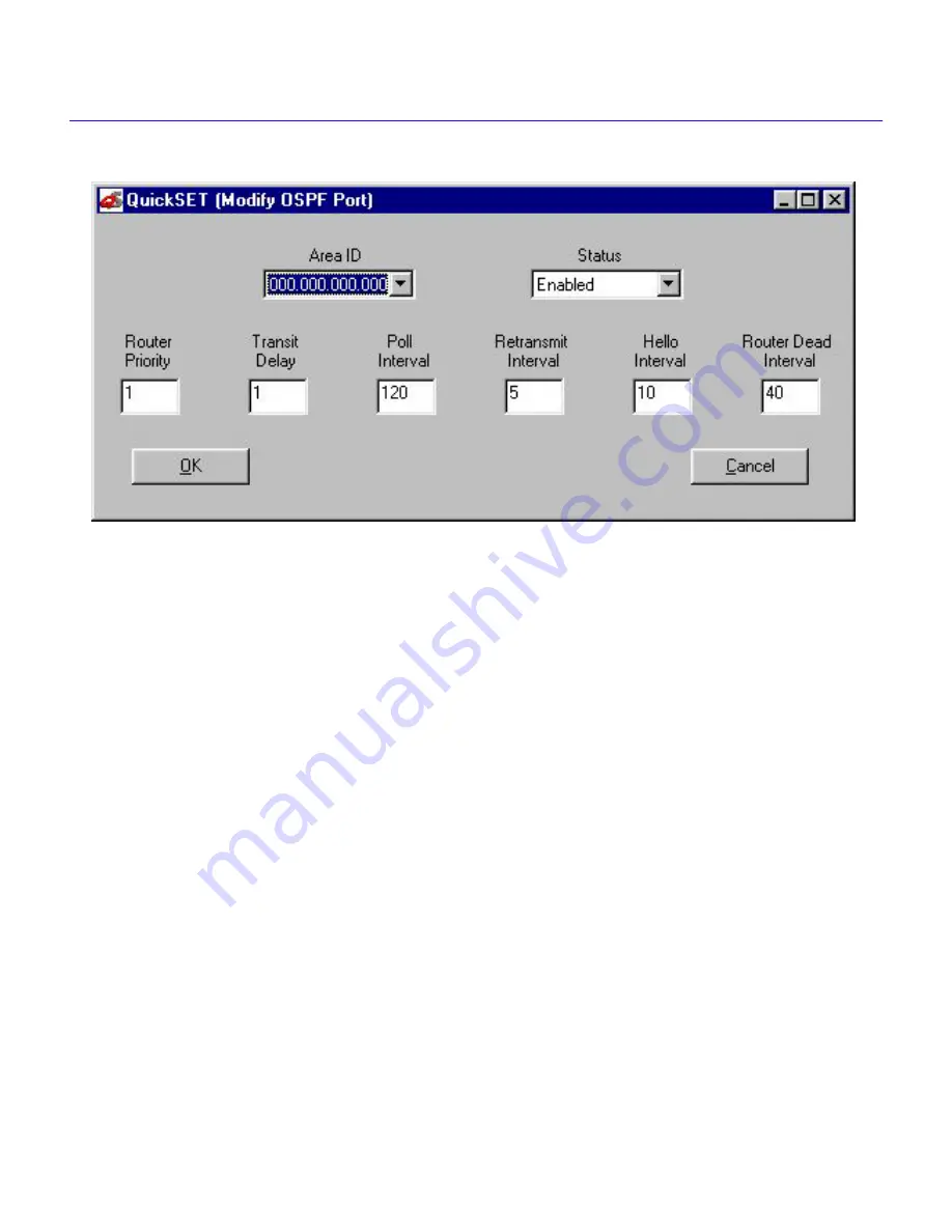
Figure 143  Modify OSPF Port

The Modify OSPF Port window shown above in 

Figure 143

, displays when you click the Modify 

button in the Area Border Routers Window. The following are definitions of the Area Border 
Routers window and Modify OSPF Port window data fields:

Port —

A MIB II Interface.

Status —

Enabled, or Disabled. When enabled, allows broadcast of link-state updates. 

Area ID —

A 32-bit number designating what area the link-state advertisement is to be received. 

An area ID of 0.0.0.0. is reserved for the backbone network.

Router Priority —

Router Priority is used (with the Router ID) to select a Backup Designated 

Router, and a Designated Router. The range of Router Priority is from 0 to 255, where 255 is the 
highest. The highest router ID is the highest router IP Address. Class C addresses are the highest.

The router with the highest priority is elected the Designated Router (DR). The router with the 
second highest priority will be elected Backup Designated Router (BDR).

Transmit Delay —

The estimated number of seconds it takes to transmit a link-state update 

packet over this interface. Link-state advertisements contained in the Link State Update packet 
will have their age incremented by this amount before transmission. This value must take into 
account transmission and propagation delays.

Summary of Contents for CSX200 CyberSWITCH

Page 1: ...QuickSET Configuration Guide for CSX200 CSX400 CSX400 DC CSX500 HSIM W6 and HSIM W84 9032691 03...

Page 2: ......

Page 3: ...anual may be trademarks or registered trademarks of their respective companies FCC NOTICE This device complies with Part 15 of the FCC rules Operation is subject to the following two conditions 1 this...

Page 4: ...service in some situations Repairs to certified equipment should be coordinated by a representative designated by the supplier Any repairs or alterations made by the user to this equipment or equipmen...

Page 5: ...y the one 1 copy of the Program provided in this package subject to the terms and conditions of this License Agreement You may not copy reproduce or transmit any part of the Program except as permitte...

Page 6: ...computer software submitted with restricted rights in accordance with section 52 227 19 a through d of the Commercial Computer Software Restricted Rights Clause and its successors and iii in all resp...

Page 7: ...he right to use only the one 1 copy of the Program provided in this package subject to the terms and conditions of this License Agreement You may not copy reproduce or transmit any part of the Program...

Page 8: ...computer software submitted with restricted rights in accordance with section 52 227 19 a through d of the Commercial Computer Software Restricted Rights Clause and its successors and iii in all resp...

Page 9: ...ICENSE You have the right to use only the one 1 copy of the Program provided in this package subject to the terms and conditions of this License Agreement You may not copy reproduce or transmit any pa...

Page 10: ...d computer software submitted with restricted rights in accordance with section 52 227 19 a through d of the Commercial Computer Software Restricted Rights Clause and its successors and iii in all res...

Page 11: ...CENELEC EN 60825 European Committee for Electrotechnical Standardization When operating within their performance limitations laser transceiver output meets the Class 1 accessible emission limit of all...

Page 12: ...5022 EN 50082 1 EN 60950 Equipment Type Environment Networking Equipment for use in a Commercial or Light Industrial Environment We the undersigned hereby declare under our sole responsibility that th...

Page 13: ...Window 18 Wide Area HDSL Configuration Window 19 Wide Area Time Slot Configuration Windows 20 Wide Area Frame Relay Time Slot Configuration Window 20 Wide Area PPP Time Slot Configuration Window 21 Wi...

Page 14: ...Port Configuration 66 Ethernet 1 and 2 Configuration Window 66 Wide Area 1 and 2 Configuration Windows 70 Wide Area T1 Configuration Window 71 Wide Area E1 Configuration Window 74 Wide Area DI Config...

Page 15: ...ttings Button 110 Bridging and Routing Configuration 111 Bridging and Routing Window 111 Firewall Window 114 Second Bridging and Routing Window 119 Routing Configuration Window 121 IP Routing Configur...

Page 16: ...36 Modify IP Host Window 137 IPX Routing Configuration Window 138 IPX Host Map Window 138 QuickSET Pull Down Menus 141 File Menu 141 Create Configuration Text File 142 Firmware Upgrade Menu 143 Runtim...

Page 17: ...QuickSET screen in the area that is highlighted in Figure 1 below If your QuickSET screen shows firmware versions 02 XX XX or greater your QuickSET configuration instructions begin at QuickSET Configu...

Page 18: ...hat your QuickSET configurable device is attached to Click OK to select the network that your device is on Figure 2 Local User Networks Window Normally QuickSET automatically establishes a communicati...

Page 19: ...HSIM W 84 the Local HSIM IP Address Window shown in Figure 5 to continue the configuration Ethernet Configuration This section explains how to configure the Ethernet 1 and 2 fields using QuickSET Not...

Page 20: ...IP Address must be entered in order to continue configuration Local Ethernet 1 and 2 Subnet Mask The Subnet Mask takes the same form as an IP address four groups of three decimal digits separated by...

Page 21: ...ess Window Local HSIM IP Address Field Displays the IP Address for the Local HSIM Ethernet interface Place the cursor in this field and type the preferred IP Address in Dotted Decimal Notation DDN for...

Page 22: ...IMs and CyberSWITCHes can support multiple IP Subnets therefore there can be multiple Secondary IP Addresses assigned to an Ethernet interface To add a Secondary IP address click on the Add button and...

Page 23: ...he fields in the System Passwords window Read Only Access This access level allows reading of device parameters not including system passwords Place the cursor in this field and type the new system pa...

Page 24: ...configuring the system passwords click on the OK button in the System Passwords window to return to the Ethernet 1 and 2 configuration window or the Local HSIM IP Address window When you have complete...

Page 25: ...Area Synchronous Configuration Window Wide Area DDS Configuration Window Wide Area HDSL Configuration Window Wide Area T1 Configuration Window The Wide Area T1 configuration window is shown in Figure...

Page 26: ...T1 Loop Back Network Loopback is a testing procedure that segments the line and allows you to isolate faults The selections for this field are No Loop and Line Loop In Line Loop all 24 channels are l...

Page 27: ...e Coding Displays the line coding for the physical E1 line The selections toggle between HDB3 and AMI The default setting for this field is HDB3 E1 Loop Back Network Loopback is a testing procedure th...

Page 28: ...ation Window section depending on which protocol you are using Wide Area DI Configuration Window The Wide Area DI configuration window is shown in Figure 10 below The following section explains how to...

Page 29: ...y is turned off The NI Port is connected to the T1 WAN interface and no timeslots are passed to the DI Port regardless of whether they are set to zero or not Figure 11 DI Telco Timing Telco Timing The...

Page 30: ...n in Figure 13 above the clock source is the WPIM DI at Site 1 DI functionality is set to Enable for both sites Transmit Clock Source must be set to Local Timing for site 1 and to Loop Timing for site...

Page 31: ...are looped back to the line The CyberSWITCH or HSIM must be in Loop Timing mode to use this option The default setting is No Loop T1 Transmit Clock Source Displays the Transmit Clock Source Click on...

Page 32: ...s determined by your service provider Factory default settings are in bold The following definitions explain the fields in the Synchronous WAN configuration window Sync Port Type Displays the Synchron...

Page 33: ...high The off setting indicates that the CTS signal is received from an external DCE The default setting is off The DSR signal is an input to the CyberSWITCH or HSIM Clicking on the box indicates that...

Page 34: ...imary and DDS CC 64K clear channel The default setting is DDS PRI DDS Clock Source Displays the DDS clock source The selections for this field are either Loop Timing or Local Timing The Loop Timing se...

Page 35: ...xt button and go to the General Configuration section of this guide Wide Area HDSL Configuration Window The Wide Area HDSL configuration window is shown in Figure 16 below Figure 16 Wide Area HDSL Con...

Page 36: ...rame Relay Time Slots A full line consists of 24 Time Slots T1 and DI or 31 Time Slots E1 each capable of up to 64 Kbps throughput If you are leasing an entire line from your service provider you may...

Page 37: ...Time Slot configuration window shown in Figure 18 displays when you click on the Next button in the Wide Area T1 or DI configuration windows if you chose PPP as the WAN Protocol Figure 19 shows the PP...

Page 38: ...ration Guide Figure 20 below shows the Line Coding window for T1 DI and E1 The window displays Line Coding for any interface number Figure 21 below shows the Modify Line Coding window Figure 20 Line C...

Page 39: ...o assign to the Time Slot If you are configuring a WPIM DI Time Slot table any available Time Slots that are set to 00 are mapped to the DI Interface If you lease an entire T1 line any Time Slots that...

Page 40: ...of 24 Time Slots each capable of up to 64 Kbps throughput If you are leasing a full line from your service provider you may select all the Time Slots by clicking the Select All button A check mark di...

Page 41: ...ickSET Configuration Guide 25 Figure 23 Line Coding Window for HDSL Figure 24 Modify Line Coding window for HDSL When you have completed Wide Area HDSL Time Slot configuration click on the Next button...

Page 42: ...ings for the CyberSWITCH or HSIM If you are configuring a CSX400 you will see the HSIM DHCP Settings window shown in Figure 26 If you are configuring an HSIM or CSX200 you will see the DHCP Settings w...

Page 43: ...leased timeout intervals Selecting Never lets you to keep your DHCP assigned IP address until the next time you boot up your PC DNS Settings Used to set up an IP address and a domain name for a Domain...

Page 44: ...Configuration with QuickSET 28 QuickSET Configuration Guide Figure 27 DHCP Settings Window for HSIMs and CSX200 CyberSWITCH...

Page 45: ...internal queue space will be made available to these packets to avoid discarding them during oversubscribed peak loads This feature is ideal for use with Inverse Multiplexing to ensure that attached r...

Page 46: ...n Guide Figure 29 Add Priority IP Address Window When you have completed General configuration be sure to save any changes you made Click on the Next button in the General Configuration window to retu...

Page 47: ...ng an HSIM you will have a single External HSIM Network window in place of the two External Ethernet 1 and 2 windows at the right of the panel The panel is identical in all other respects The followin...

Page 48: ...uting check box allows you to turn on off IPX Routing External Ethernet 1 Network This field External HSIM Network Number for HSIM W6 and W84 displays the IPX network number assigned to the external E...

Page 49: ...ves a packet addressed to 192 168 53 4 host C puts an ARP broadcast on the LAN asking the host of that address to respond with its MAC Machine Address and Control Layer address Because host A is not o...

Page 50: ...stination address of a packet The upper layer protocol type of a packet such as TCP UDP ICMP or all TCP IP protocols The TCP or UDP port number of a packet Interface Number When an IP Access Control L...

Page 51: ...fields Click OK when you have finished entering the data Your new firewall entry will appear in the Firewall Configuration Window Figure 35 Modify Firewall Entry Window The Modify Firewall Entry wind...

Page 52: ...ist allows all traffic to pass Entering a mask of 255 255 255 255 causes only packets matching the exact address you have entered to match the filter For a Class C address entering a mask of 255 255 2...

Page 53: ...K button below the Interface ACL window to apply the Interface ACL changes When you have completed the Firewall configuration click on the Done button to return to the Bridging and Routing Configurati...

Page 54: ...elect a WAN Frame Type for each interface Figure 36 Bridging and Routing WAN Frame Type Configuration Window The Bridging and Routing window displays fields for each interface number and its associate...

Page 55: ...37 below allows you to select one of three frame types to be used over the WAN for each interface Native WAN Encapsulated Ethernet and Encapsulated Ethernet SNAP Select the WAN Frame Type that you wi...

Page 56: ...ion of the Routing configuration window Interface Displays an interface number assigned an IP subnet Remote LAN Subnet Displays the IP subnet assigned to the interface number Subnet Mask Displays the...

Page 57: ...nformation on how to use the features of this window Split Horizons Window The Split Horizons window shown in Figure 39 displays after clicking the Split Horizons button in the Bridging and Routing wi...

Page 58: ...be assigned an IPX network number Network Displays the active IPX network number assigned to an interface Host Map The IPX Host Map button takes you to the IPX Host Map window IPX Host Map entries are...

Page 59: ...ce number a two digit decimal number related to the Frame Relay Time Slot DLCI Displays the Data Link Connection Identifier Use this field to enter the DLCI which is a three digit decimal number from...

Page 60: ...below in Figure 42 Use the scroll button in the Interface Number window to find a clear data field After entering your changes click OK to return to the IPX Host Map window Modify This button displays...

Page 61: ...o exit QuickSET Advanced Routing Configuration Window Figure 44 Advanced Routing Configuration Window The Advanced Routing configuration window shown in Figure 44 above displays after you click on the...

Page 62: ...leading into the Telco central office A Subnet Mask is required for this IP address before you can use this link Subnet Mask Displays the subnet mask for the Local WAN IP address Modify Use this butto...

Page 63: ...igure 46 below displays after clicking on the NAT Settings button in the Advanced Routing configuration window Figure 46 NAT Settings Configuration Window The NAT Settings window is used to set up Net...

Page 64: ...To enable NAT click the pull down menu button and select an interface number to run NAT through Figure 47 HSIM NAT Settings Configuration Window Add Proxy Allows you to add NAT proxy servers Click th...

Page 65: ...anced Routing configuration window The Redirector window is used to set up an IP address for a remote Dynamic Host Configuration Protocol DHCP server Figure 49 Redirector Window IP Host Map Window The...

Page 66: ...Window Use the Interface Number scroll button to select an Interface Number Enter the DLCI Data Link Connection Identifier number in the DLCI window The DLCI number is the identifier for the virtual...

Page 67: ...ging to a single Autonomous System AS In an Autonomous System routers exchange routing information through a common routing protocol An Autonomous System may contain one or more networks but each netw...

Page 68: ...age displays a database of areas Areas are represented by an address area ID similar to an IP address in format four groups of three decimal numbers separated by periods There is no mask associated wi...

Page 69: ...nterface Configuration Window shown in Figure 55 below displays a database of Area Border Routers and relevant operating parameters Definitions of these parameters are presented on the following pages...

Page 70: ...e network Router Priority Router Priority is used with the Router ID to select a Backup Designated Router and a Designated Router The range of Router Priority is from 0 to 255 where 255 is the highest...

Page 71: ...lo packets that the router sends on this interface advertised in Hello packets sent out of this interface Router Dead Interval The number of seconds before the router s neighbors will declare it down...

Page 72: ...incorrectly specify the any of the parameters i e subnet mask Destination or Next Hop defining the static route in the Add Route window QuickSET checks the IP address and Mask and will not accept an...

Page 73: ...ns initiate TFTP BootP Services and configure Compression and Congestion Settings for your CyberSWITCH or HSIM File Menu This section describes the pull down menu options from the File menu as shown i...

Page 74: ...n in Figure 63 displays after clicking on the File pull down menu and selecting Restore Configuration at the top of any QuickSET configuration window The Restore Configuration window allows you to loa...

Page 75: ...e As window shown above Click Save to save the file and return to the configuration window from which you selected the File Menu Telnet This menu item launches the Telnet application window used to in...

Page 76: ...mmunity The Community field allows you to enter the Community password of you CyberSWITCH or HSIM Gateway IP Address Use the Gateway IP Address field to enter the IP Address of the server acting as a...

Page 77: ...onfiguration menu as shown in Figure 67 Figure 67 Runtime Configuration Menu Compression and Congestion Window The Compression and Congestion window shown in Figure 68 displays after you click on the...

Page 78: ...e CyberSWITCH or HSIM supports data compression on all DS0s which is equivalent to two full T1 lines The Modify Compression and Congestion Window Figure 69 displays when you click the Modify button in...

Page 79: ...scroll list then click the compression check box Clicking the OK button applies the changes to the interface When you have completed compression configuration click on the Save button to save any cha...

Page 80: ...firmware version number appears on the first QuickSET screen in the area that is highlighted in Figure 71 below If your QuickSET screen shows firmware versions 02 00 xx or greater your QuickSET config...

Page 81: ...with the CyberSWITCH that you wish to configure and displays the IP Address window shown below in Figure 73 However under certain circumstances QuickSET may not be able to locate the device automatica...

Page 82: ...isplays after clicking on the Next button in the Introductory window The Local Ethernet IP address and Subnet Mask fields shown on the Ethernet 1 and 2 configuration window are used for setting an IP...

Page 83: ...f three decimal digits separated by periods Each group must be in the numerical range of 0 to 255 If you wish to use a different Subnet Mask enter it at this time in DDN format Local Ethernet 1 and 2...

Page 84: ...s therefore there can be multiple Secondary IP Addresses assigned to an Ethernet interface To add a Secondary IP address click on the Add button and enter the IP Address and Subnet Mask in their corre...

Page 85: ...t are used in Local Management through a TELNET application System passwords allow you to control management access by establishing three passwords Each password controls a different level of access F...

Page 86: ...firm Password field below the QuickSET SuperUser field When you have finished configuring the system passwords click on the OK button in the System Passwords window to return to the Ethernet 1 and 2 c...

Page 87: ...ow Wide Area T1 Configuration Window The Wide Area T1 configuration window is shown in Figure 78 below Figure 78 Wide Area T1 Configuration Window This section explains how to configure the Wide Area...

Page 88: ...Loop Timing Protocol The Protocol panel lets you select one of four protocols Point to Point HDLC High Level Data Link Control Frame Relay Point to Point Frame Relay Point to Multipoint High Level Dat...

Page 89: ...ws QuickSET Configuration Guide 73 Figure 79 DLCIs and Add DLCI Windows When you have completed Wide Area T1 configuration click on Next and go to the Wide Area Time Slot Configuration Windows section...

Page 90: ...HDB3 and AMI The default setting for this field is HDB3 E1 Loop Back Network Loopback is a testing procedure that segments the line and allows you to isolate faults Click on the radio button to selec...

Page 91: ...ield displays Q 933 Annex A T1 617 Annex D and T1 617 Annex D 1994 The default for Frame Relay is T1 617 Annex D This field is grayed out and not used for PPP DLCI Setup Button The DLCI Setup button d...

Page 92: ...a DI Drop and Insert Port DI Functionality Enable The NI Port is connected to the T1 WAN connection Any timeslot set to zero will pass that timeslot from the NI Port to the DI Port see Figure 83 on t...

Page 93: ...Circuit Timing The configuration shown above in Figure 84 describes Tail Circuit Timing The Tail Circuit has the PBX as its timing source in Site 1 The DI functionality for Site 1 is set to Data From...

Page 94: ...ervice provider recommends another setting The default setting for this field is 0 dB Click on the appropriate radio button for the following levels 0 Zero dB 7 5 dB and 15 dB T1 Line Coding Displays...

Page 95: ...k Management Protocol If you selected Frame Relay protocol this field displays Q 933 Annex A T1 617 Annex D and T1 617 Annex D 1994 The default is T1 617 Annex D When you have completed Wide Area DI c...

Page 96: ...tions explain the fields in the Synchronous WAN configuration window Sync Port Type Displays the Synchronous port electrical interface type The selections for this field are V 35 RS422 RS232 and X 21...

Page 97: ...oint HDLC High Level Data Link Control Frame Relay Point to Point Frame Relay Point to Multipoint High Level Data Link Control lets you select either Full or Fractional mode for all or half of the tim...

Page 98: ...T 82 QuickSET Configuration Guide Figure 88 DLCIs Window Figure 89 Add DLCI Window When you have completed Wide Area Synchronous configuration click on the Next button and go to the Interfaces Window...

Page 99: ...ce provider The factory default settings are in bold This section describes the fields in the Wide Area DDS configuration window DDS Line Mode Displays the DDS Line Mode The selections for this field...

Page 100: ...ay Point to Multipoint High Level Data Link Control lets you select either Full or Fractional mode for all or half of the time slots for a single interface number and alias Point to Point protocol let...

Page 101: ...I Window When you have completed Wide Area DDS configuration click on the Next button and go to the Interfaces Window section of this guide Wide Area HDSL Configuration Window The Wide Area HDSL confi...

Page 102: ...t protocol lets you select an interface number for each time slot Frame Relay Point to Multipoint allows only one interface number and alias but allows multiple DLCIs Frame Relay Point to Point allows...

Page 103: ...a ISDN Configuration Window The Wide Area ISDN Configuration Window shown is in Figure 96 below Figure 96 Wide Area ISDN Configuration Window The Wide Area ISDN window lets you select ISDN Profiles an...

Page 104: ...ly you with two one or no SPID numbers One SPID number may be assigned to each ISDN B Bearer channel one SPID for both ISDN B channels or SPIDs may not be provided at all depending on the type of digi...

Page 105: ...uration Windows QuickSET Configuration Guide 89 Figure 97 Warning Message Use the Profile Wizard window shown in Figure 98 below to enter the number of Primary Profiles you require Figure 98 First ISD...

Page 106: ...number Click OK when you have finished Figure 99 Second ISDN Profile Wizard Window The Create Settings message shown below in Figure 100 displays after you have selected the number of Primary and Sec...

Page 107: ...le Button The Modify Profile button will display the Modify Profile window shown in Figure 101 above The Modify Profile window lets you modify the individual parameters of the profile currently displa...

Page 108: ...interface Samples Required The number of samples required to initiate bandwidth expansion or reduction Line Utilization Threshold The percentage of available bandwidth that will be allowed before ano...

Page 109: ...ion One of the routers referred to as the authenticator challenges the other router referred to as the peer by generating a random number and sending it along with the system name The peer then applie...

Page 110: ...remote router s password and returns acknowledgment When you select PAP you will need to supply your Local Name and Local to Remote Password and the Remote Name and Remote to Local Password None If yo...

Page 111: ...wn in Figure 104 on the following page displays when you click on the Next button in the Wide Area E1 configuration window Figure 103 Frame Relay Time Slot Configuration Window T1 DI Frame Relay Time...

Page 112: ...tion window E1 Clicking the Line Coding button displays the Line Coding window For an explanation of line coding functions see Line Coding section When you have completed Wide Area Frame Relay Time Sl...

Page 113: ...05 displays when you click on the Next button in the Wide Area T1 or DI configuration windows if you chose PPP as the WAN Protocol The Wide Area Time Slot configuration window shown in Figure 106 disp...

Page 114: ...ble Time Slots that are set to 00 are mapped to the DI Interface If you lease an entire T1 line any Time Slots that are not used in the Wide Area PPP Time Slot configuration window are used by the dev...

Page 115: ...me Slot A full line consists of 24 Time Slots each capable of up to 64 Kbps throughput If you are leasing a full line from your service provider you may select all the Time Slots by clicking the Full...

Page 116: ...oyed A T1 module will employ 24 time slots whereas an E1 module will employ 31 time slots Time Slots A full line consists of 24 Time Slots T1 and DI or 31 Time Slots E1 each capable of up to 64 Kbps t...

Page 117: ...1 contains 32 interfaces vs 24 for T1 and DI The Line Coding window lets you select one of three coding setups None No Line Coding is applied to the selected interface the the interface s time slots a...

Page 118: ...window is shown below in Figure 110 Figure 110 General Configuration Window DHCP Settings Configuration Window The DHCP Settings configuration window shown in Figure 111 below displays after clicking...

Page 119: ...de 103 The DHCP Settings configuration window is used to configure DHCP settings for the CyberSWITCH or HSIM If you are configuring an HSIM or CSX200 you will see the window shown below in Figure 112...

Page 120: ...dress until the next time you boot up your PC DNS Settings Used to set up an IP address and a domain name for a Domain Name server WINS Servers Windows Internet Name Service WINS resolves NETBIOS comp...

Page 121: ...button and the Add Priority IP Address screen shown in Figure 114 appears Enter the IP Address es that are to receive priority treatment in the IP Address window You can use the IP Address window scro...

Page 122: ...Alias Setup Button Click the Alias Setup button to display the Interface Alias window shown in Figure 116 below The Interface Alias Window displays a list of Interface Numbers and their assigned alias...

Page 123: ...face are displayed in the center of this window You can scroll down the list of interfaces using the scroll button at the right of the data field and display the connection parameters of the highlight...

Page 124: ...h over from the back up interface The default value is 90 seconds Allowed values are in increments of five seconds up to a maximum of 10 000 seconds A value of zero is acceptable Connect Retries Conne...

Page 125: ...rameter for each Dial Up interface Figure 119 Dialup Settings and Modify Windows The Modify Dial up Setting window lets you modify a Dial up Setting entry highlighted in the Dial up Settings window Us...

Page 126: ...ts locally lets the connection close down saving the cost of keeping a circuit alive when there is no traffic Clicking the Spoofing Settings button displays the Spoofing Settings Window shown below in...

Page 127: ...irst Bridging and Routing window Inverse Mux Multiplex Configuration This function lets you balance your LAN traffic between two T1 WAN ports and is used with Point to Point Protocol PPP or HDLC proto...

Page 128: ...e check box to turn on IP Routing IPX Routing The IPX Routing check box allows you to turn on off IPX Routing Click on the check box to turn IPX Routing on External Ethernet 1 Network This field displ...

Page 129: ...ives a packet addressed to 192 168 53 4 host C puts an ARP broadcast on the LAN asking the host of that address to respond with its MAC Machine Address and Control Layer address Because host A is not...

Page 130: ...Access Control List ACL is enabled on a router port each packet forwarded out this port is first checked against the ACL If the address es of a packet match the address es in the first filter in the l...

Page 131: ...Bridging and Routing Configuration QuickSET Configuration Guide 115 Figure 125 Firewall Window Figure 126 Add Firewall Entry Window...

Page 132: ...will appear in the Firewall Configuration Window Figure 127 Modify Firewall Entry Window Use the Interface Firewall Configuration panel lower half of Firewall window shown in Figure 128 to assign an I...

Page 133: ...e IP field and type the IP address of the source for which you wish to set permissions Source Mask Displays the mask for the Source IP address specified in the Source IP field To set the mask for the...

Page 134: ...er permits or denies traffic to and from a specified source or destination Port Enter the port number in this field to create an access control filter that applies only to traffic for a specific TCP o...

Page 135: ...pe for router to router communication Select the Encapsulated Ethernet or Encapsulated Ethernet SNAP frame types for router to bridge or bridge to bridge communication To change the WAN Frame Type inf...

Page 136: ...SNAP Select the WAN Frame Type that you wish to enable by clicking the appropriate radio button When you are done click the OK button The OK button returns you to the Bridging and Routing WAN Frame Ty...

Page 137: ...uting Otherwise refer to IPX Routing Configuration section to configure the device for Novell IPX routing IP Routing Configuration This section describes the fields in the IP Routing Configuration por...

Page 138: ...ter you wish to designate as the default route Add Route This button allows you to add a route and to configure the device to forward only those packets from the specified route Delete This button del...

Page 139: ...is button to change an entry in the Advanced Routing Options window Split Horizons Window The Split Horizons window shown in Figure 134 below displays after clicking the Split Horizons button in the B...

Page 140: ...irector button in the Advanced Routing configuration window The Redirector window is used to set up an IP address for a remote Dynamic Host Configuration Protocol DHCP server Figure 135 Redirector Win...

Page 141: ...d NAT proxy servers Click the Add Proxy button and an Add NAT Proxy Server window Figure 137 below will appear Enter an IP Address and select a Port number type and a Protocol for each server entry De...

Page 142: ...ng and receiving of Routing Information Protocol packets Routing Information Protocol is used in IP for broadcasting open path information between routers to keep routing tables current Figure 138 Dis...

Page 143: ...ould be noted that RIP 2 is not intended to be a substitute for OSPF Open Shortest Path First protocol in large autonomous systems The restrictions on autonomous system diameter and complexity which a...

Page 144: ...load RIP is intended to allow routers to exchange information for computing routes through an IP based network Any router that uses RIP is assumed to have interfaces to one or more networks otherwise...

Page 145: ...epends on knowing the precise subnet mask which would be ignored by a RIP 1 router Compatibility Switch A compatibility switch is necessary for two reasons First there are implementations of RIP 1 in...

Page 146: ...mous System AS In an Autonomous System routers exchange routing information through a common routing protocol An Autonomous System may contain one or more networks but each network within the AS may o...

Page 147: ...atabase Figure 140 OSPF Settings Window The OSPF Settings window shown in Figure 140 above displays a database of areas Areas are represented by an address area ID similar to an IP address in format f...

Page 148: ...button will delete the area highlighted in the database in the OSPF Settings Window The OSPF Interface Configuration window shown in Figure 142 below displays a database of Area Border Routers and re...

Page 149: ...network Router Priority Router Priority is used with the Router ID to select a Backup Designated Router and a Designated Router The range of Router Priority is from 0 to 255 where 255 is the highest...

Page 150: ...lo packets that the router sends on this interface advertised in Hello packets sent out of this interface Router Dead Interval The number of seconds before the router s neighbors will declare it down...

Page 151: ...he route to be redistributed and click OK when you have finished Figure 145 Add Route The IP Route Warning message shown below in Figure 146 will appear if you incorrectly specify the any of the param...

Page 152: ...Enter the new data into the respective windows and click OK when you have finished You will return to the OSPF Redistribute Routes window You may select another route to Add Delete or Modify or Click...

Page 153: ...the virtual circuit present on the interface On an interface configured for Frame Relay this number is the DLCI for the IP Address at the end of the circuit Enter the IP Address of the host in the IP...

Page 154: ...nge an entry in the IPX Routing Configuration window Select the interface number to modify by clicking on the tab to the left of the interface number IPX Host Map Window The IPX Host Map window shown...

Page 155: ...s a three digit decimal number from 16 to 991 inclusive corresponding to the WAN virtual circuit connection to the Telco central office WAN Network Displays the active IPX network number of the WAN co...

Page 156: ...dd IPX Host Window When you have finished making changes click the OK button to exit the IPX Host Map window and return to the IP IPX Routing Configuration window When you have completed your configur...

Page 157: ...r CyberSWITCH or HSIM File Menu This section describes the File Menu pull down menu options shown below in Figure 153 Figure 153 File Menu Store Configuration The Store Configuration window shown in F...

Page 158: ...stored configuration into QuickSET where it can be loaded into your device and saved Figure 155 Restore Configuration Window Create Configuration Text File The window shown in Figure 156 appears when...

Page 159: ...Menu TFTP BootP Services The TFTP BootP Services window shown in Figure 157 below displays after clicking on the Firmware Upgrade pull down menu and selecting TFTP BootP Services at the top of any Qui...

Page 160: ...ress indicates the IP address of the PC running this utility File Name The File Name field indicates the location and name of the firmware image you are putting on your CyberSWITCH or HSIM DownLoad Th...

Page 161: ...tending the link bandwidth To use data compression the CyberSWITCH or HSIM must first be fully configured and connected to a live WAN link and compression must be configured on any remote WAN device s...

Page 162: ...data a user may offer to the network during a calculated time interval Data is guaranteed not to be discarded by the network Excess Burst Displays the Excess Burst size which is the maximum amount of...

Page 163: ...Date window shown in Figure 161 displays when you click on the Runtime Configuration item in the menu bar and click on Set Device Time and Date Figure 161 Set Device Time and Date Window Enter the new...

Page 164: ...Configuration with QuickSET 148 QuickSET Configuration Guide...

Reviews: