CCD-Premium
Operating manual
page 20 /24
spindle accessories
In the packaging of the spindle you will find a pressure
foot and a depth limiter, and cleaning utensils and the
spindle guide.
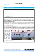
pressure foot
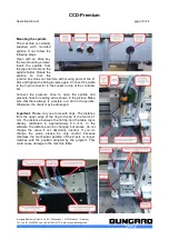
This part serves to press down the board before the drill
hits them. This is particularly useful if the board is not
completely flat or when you drill more than one board
(you can drill 3 boards each with 1.6 mm thickness in the
stack). In addition, this pressure shoe serves as
protection for your fingers against the rotating tool. The
pressure foot can remain mounted when changing tools.
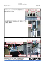
It is fastened with three screws on the suction head. In
the future there will be a quick-change version with a
magnetic mount to enable a fast change between the
depth limiter and the pressure foot. A short exchange
instructions as well as a video on how to change from
pressure foot to depth limiter is available from us.
depth limiter (FTB)
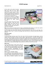
During the milling procedure the depth limiter (FTB)
glides over the surface of the pcb ensuring perfect
equality of the routing depth even with uneven surfaces.
The limiter is designed for use with our delivered routers,
especially for the G30 and G60 V-Cut-Routers.
The milling depth is not compatible with the cooling
device for routing aluminium.
In the following, we first assume that the Z-axis lifted, as
after a reference drive. Leave the spindle in the holder
and insert a tool.
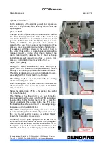
Screw the depth limiter (FTB) to the suction. Be careful
not to touch the tool
The FTB has a fine thread and a lock nut. Solve the
latter and unscrew the lower part of the FTB up or down
to adjust the height. Fasten the lock nut to lock the
height adjustment. The conical part of the FTB scans
the board surface. We recommend to manually change
tools when using the depth limiter.
The FTB is not required for drilling and cut-out-routing
(countour routing) and should thereby be removed. For
this you do not need to change the setting. Simply
loosen the 3 mounting screws again.
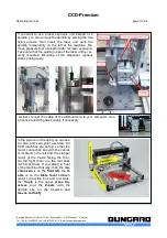
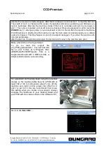
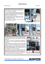
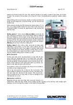
On the Fig. On the upper right you can be see next to
the spindle the ball screw of the Z-axis. The guiding rail
of the ball screw is coupled via a small aluminium bar to
the spindle support. If you loosen the thumbscrew and
slide the aluminium bar to the right, you can move the
Bungard Elektronik GmbH & Co. KG, Rilkestraße 1, 51570 Windeck – Germany
Tel.: +49 (0) 2292/5036, Fax: +49 (0) 2292/6175, E-mail: [email protected]

