
CCD-Premium
Operating manual
page 23 /24
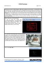
layer of your PCB. We recommend to place the reference holes outside the design, at best on the long
side of the PCB. In our software IsoCam an automatic function to generate these reference holes is in -
cluded .
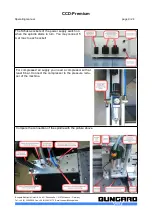
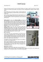
The drill backing board needs to be thick enough to provide a secure grip for the reference pins/rivets.
A 6 mm MDF board is recommended. Instead of steel pins (which stick out of the board and possibly
interfere with the milling action), we prefer rivets. The flat head of these rivets is almost level with the
PCB and does not interfere with the depth limiter.
This fixing method has two advantages: The board is held securely, even for a later cutting out the PCB
from the raw material. And a perfect match between top and bottom of the milled board is ensured by
the fact that the mirror axis in the software and the physical mirror axis of the reference holes match ex-
actly.
Also use reference pins in the wet process technique, if you first drill the board, then remove the board
from the machine to make through hole plating and etch the tracks and after that return to the machine
to make the final cut out routing.
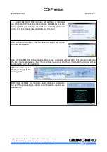
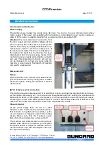
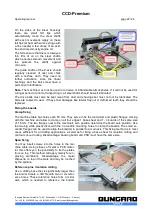
Adhesive tape
simplest, fastest and cheapest method. The adhesive tape can be drilled and routed without problems.
In contrast to the clamping and span-method, you can process only one board at a time. If you need to
reference a double sided PCB, you can use the fiducial recognition option of RoutePro3000.
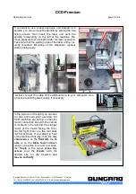
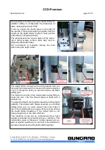
Vacuum fixation
As an option all CCDS can be equipped with a vacuum table. This table can be connected to a vacuum
pump (membrane or better: side channel pump) or a vacuum cleaner. The vacuum table sucks through
the mounting holes of the CCD-table. You can put an MDF-drill backing board on the table and close
the remaining fixing holes with foil or screws. The MDF is permeable to air, but you can enhance the
vacuum effect by drilling small suction holes in the MDF.
Vacuum fixation is handy when processing flexible and semi-flexible materials. However, a possible
bow in the board and tolerances in the material is not compensated. Thus the use of the depth limiter is
still recommended.
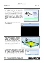
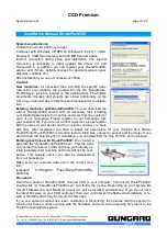
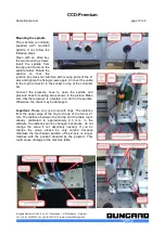
Drilling bare boards
When making double sided PCBs with chemical through hole plating, the first step is to drill the holes.
Any photo processing of tracks and pads will follow later.
Use a raw cut piece of copper clad laminate and put it, together with a base sheet of the same size, on
the machine table. Align to the X- or Y-axis and fix like described under "clamp fixing".
Alternative: Use a big base sheet and fix it by use of the plastic disks. Put the board to be drilled on top
and push it to the machine's zero position. Using adhesive tape, fix the board to the base sheet. Ad-
vantage: The fixture position is independent from the board size. The adhesive tape can be drilled
through without damage to the drill.
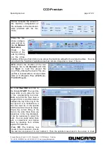
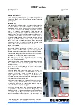
Pre-sensitized base material
In the same way as above, pre-sensitized base material still covered with its protection foil may be
drilled
prior to exposure
. As to our experience, this gives best results: There is only one positioning
operation necessary at exposure time. The drilled image will perfectly fit the etched board structures. If
possible produce your artwork with
transparent drill holes
in the pads. This will make the referencing
process very simply.
Etched PCBs
The board already shows the tracks and pads. The drilling must exactly fit the pads.
Bungard Elektronik GmbH & Co. KG, Rilkestraße 1, 51570 Windeck – Germany
Tel.: +49 (0) 2292/5036, Fax: +49 (0) 2292/6175, E-mail: [email protected]


