CCD-Premium
Operating manual
page 22 /24
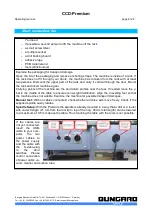
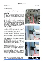
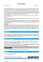
On the sides of the linear housings
there are small felt tips which
automatically clean the steel shafts
with each movement. Apply on these
felt tips (at best with some syringe with
a fine needle) a few drops of an acid-
free and low-viscosity engine oil.
The felts ensure that there is always a
thin film of oil on the steel shafts,
which ensures smooth movement and
the protects the shafts against
corrosion.
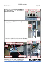
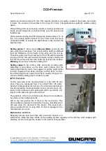
The guide shafts of the Z-axis should
regularly cleaned of dust and chips
with a lint-free cloth. They need no
further lubrication, since the linear
bushings and the ball screw have a
permanent lubrification.
Note
: The machine must not be used in corrosive or inflammable atmospheres. If it will not be used for
a longer period or prior to transporting it, all steel shafts should be well lubricated.
The drive belts must also be kept clean from dust and shavings but must not not be lubricated. The
belts are subject to wear. If they show damages like lateral fray-out or deformed teeth they should be
replaced.
Fixing the boards
Clamp fixing
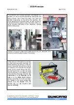
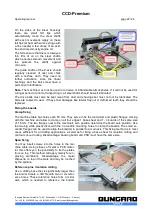
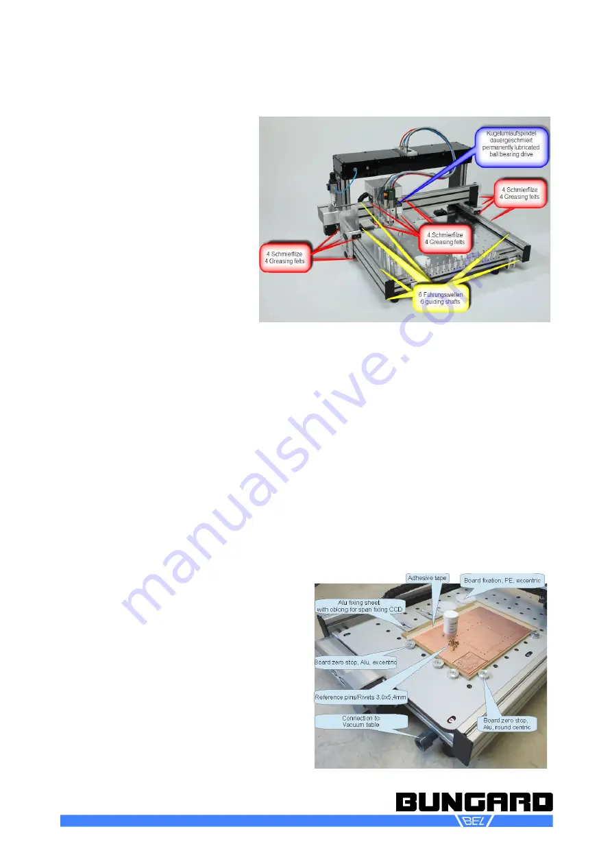
The machine table has holes each 50 mm. They serve to fix the aluminium and plastic flanges coming
with the machine and allow to clamp on all four edges 1 base sheet and 1 - 3 boards of the same size
of 1.5 mm. The two flanges near to the machine's zero position determine the board zero position. Use
the two big white plastic discs with the 3 eccentric mounting holes to clamp the boards. The small ec -
centric flanges can be used to align the board(s) in parallel to a main axis. This fixing method is in most
cases sufficient for all drilling applications, as well as for fixing a base sheet for isolation milling and
contour cut-out routing. Disadvantage: backing board and PCB must have the same size.
Span fixing
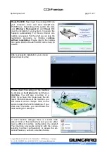
You may insert screws into the holes in the ma-
chine table. Using stripes of metal or PCB mater-
ial, this offers you the possibility to fix the plates
from on top. This method will apply mainly for en-
graving aluminium. Disadvantage: the metal
stripes lie on top of the plate and may be touched
by the spindle.
Reference pins / Isolation milling
Use a drilling base that is significantly larger than
the board. Create a drill file with two or six refer-
ence holes. These reference holes form a mirror
axis, which is needed to reference the bottom
Bungard Elektronik GmbH & Co. KG, Rilkestraße 1, 51570 Windeck – Germany
Tel.: +49 (0) 2292/5036, Fax: +49 (0) 2292/6175, E-mail: [email protected]

