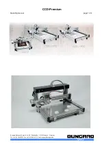

CCD-Premium
Operating manual
page 15 /24
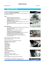
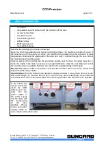
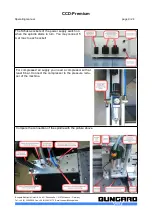
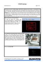
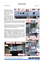
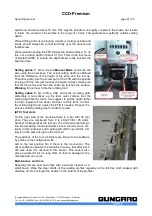
We generally recommend to use a depth limiter for
isolation milling to compensate the tolerances of
table, backing board and PCB.
To do so, loosen the thumb screw on the right of
the spindle. This will decouple the spindle from the
z-axis, so the depth limiter is able to float over the
pcb surface (compare pictures).
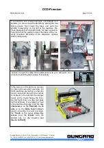
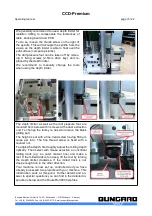
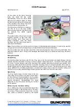
The drill pressure foot can be taken off by remov-
ing 3 fixing screws (2.5mm Allen key) and re-
placed by the depth limiter
We recommend to manually change the tools
when using the depth limiter.
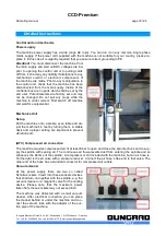
The depth limiter as well as the drill pressure foot are
mounted from below with 3 screws at the dust extraction
unit. To change the tools you need to remove the black
gliding part.
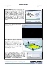
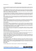
The height is set with a fine tread screw having 500 µm
slope per turn. The fine thread screw is fixed with a
counter nut.
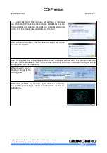
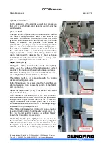
To adjust the depth, first roughly adjust the milling depth
optically. Then select with mouse selection an uncritical
milling track (e.g. an outer contour line) and make a
test. If the milled track is too deep, lift the tool by turning
the depth limiter clockwise. If the milled track is not
deep enough turn in the other direction.
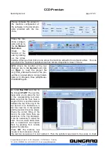
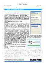
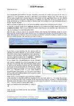
Your machine is now set up, controlled and you have
already processed two projects with your machine. This
introduction ends at this point. Further details and an-
swer to special questions you can find in the detailed in-
structions below and the RoutePro3000 help files.
Bungard Elektronik GmbH & Co. KG, Rilkestraße 1, 51570 Windeck – Germany
Tel.: +49 (0) 2292/5036, Fax: +49 (0) 2292/6175, E-mail: [email protected]


