background image

For qualified technicians

Please read carefully prior 
to installation and mainte-
nance


CAUTION!

Observe the safety instructions of this installation and 
maintenance manual before placing the boiler in oper-
ation.

DANGER!

If installation, adjustment, modification, operation or 
maintenance of the heating system is carried out by 
an unqualified person, this may result in danger to life 
and limb or property damage. The directions of this 
installation and maintenance manual must be fol-
lowed precisely. Contact a qualified service com-
pany, service provider or the gas company if support 
or additional information is required.

CAUTION!

The operating manual is a component of the techni-
cal documentation and must be handed over to the 
operator of the heating system. Discuss the instruc-
tion in this manual with the owner or operator of the 
heating system to ensure that they are familiar with all 
information required for operation of the heating sys-
tem. If the boiler will be installed in Massachusetts, it 
must be installed by an installer or dealer who is reg-
istered there.

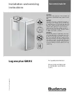
Installation and servicing 
instructions

Gas condensing boiler

Logano plus GB312

 7 74

7 010

 719 - 0

6

/2009

 US 

Summary of Contents for Logano plus GB312

Page 1: ... precisely Contact a qualified service com pany service provider or the gas company if support or additional information is required CAUTION The operating manual is a component of the techni cal documentation and must be handed over to the operator of the heating system Discuss the instruc tion in this manual with the owner or operator of the heating system to ensure that they are familiar with al...

Page 2: ... return 32 6 9 6 Installing the DHW Tank 32 6 9 7 Installing the condensate drain 33 6 10 Filling the heating system and checking for leaks 34 6 11 Connecting the fuel supply 36 6 11 1 Installing gas feed 36 6 11 2 Installation at high altitudes 37 6 12 Electrical connections 38 6 12 1 Connecting the main power supply 38 6 12 2 Leveling the boiler 40 7 Recommissioning the heating system 41 7 1 Che...

Page 3: ...cleaning them 59 9 6 1 Determining the extent of contamination 59 9 6 2 Cleaning the burner and heat exchanger 61 9 7 Checking gas valve for leaks 67 9 8 Checking for leaks during normal operation 69 9 9 Testing ionization current 69 9 10 Concluding servicing maintenace 69 9 10 1 Removing instruments 69 9 10 2 Fitting outer casing components 69 9 10 3 Confirming servicing maintenance 69 9 11 Servi...

Page 4: ...mple where there is a masonry or prefabricated chimney flue Danger of explosion of flammable gases V Any work on components that carry gas may only be carried out by an approved heating contractor Dangers posed by explosive and easily combusti ble materials V Do not use or store easily combustible materials paper lace curtains clothing thinners paints etc near the boiler V Maintain a clearance of ...

Page 5: ...tal safety of the heating system V Use only genuine spare parts Damage caused by the use of parts not supplied by Buderus is not covered by the Buderus warranty Instructing the customer V Explain to the customer how the boiler works and how to operate it V Inform the customer that he she must not carry out any alterations or repairs 1 2 Explanation of symbols Signal words are used to indicate the ...

Page 6: ...egulations The boiler must be serviced annually Boiler operating conditions The heat exchanger has been designed and certified in accordance with the ASME Boiler and Vessel Code Sec tion IV Maximum boiler temperature 200 F Maximum operating pressure 50 psi The hot water piping system must comply with the appli cable legislation and regulations If an existing boiler is replaced the complete hot wat...

Page 7: ...ce or an attic the hard wired carbon monoxide detector with alarm and battery back up may be installed on the next adjacent floor level b In the event that the requirements of this subdivision can not be met at the time of completion of installation the owner shall have a period of thirty 30 days to comply with the above requirements provided however that dur ing said thirty 30 day period a batter...

Page 8: ...tion and maintenance of the boiler you will require the standard tools used for central heating and gas and water systems plus set of a metric wrenches and hex keys The following may also prove useful The RC35 programming unit is required as a monitor ing device for commissioning servicing and maintain ing the boiler 2 pipes approx 1 approx 6 6 ft long for carrying the boiler or 5 pipes approx R1 ...

Page 9: ...ve supplied as standard not factory installed 11 Mating flange 2 included in B kit not factory installed 12 Bolts washers Lock washers and nuts to mount supply manifold and mating flanges The main components of the Logano plus GB312 Æ Fig 1 are Programmer Frame and jacket Boiler heat exchanger with insulation Gas burner B kit standard B kit comprising temperature pressure gauge pressure relief val...

Page 10: ...splay button 11 Flue gas test button 12 Reset button Logamatic BC10 basic programmer Æ Fig 2 The Log amatic BC10 basic programmer enables basic operation of the heating system It provides functions such as the following for that purpose Turning the heating system on off Setting the DHW temperature and the maximum boiler temperature in heating mode Status display On overall picture of the controls ...

Page 11: ... manner Accessories A wide range of accessories for the boiler is available Refer to the catalog for precise details of suitable acces sories The following accessories are available from the trade Flue system Air supply system Programming unit e g RC35 Component Packaging Boiler fully assembled with outer casing Logamatic MC10 program ming unit BC10 and gas isolating valve 1 box on a pallet Techni...

Page 12: ...onnection RK Boiler return TM Pressure temperature gauge Boiler size output no of heat exchanger sections Unit 90 4 120 4 160 5 200 6 240 7 280 8 Width B Inches 39 1 47 3 55 5 Dimension XAA Inches 13 1 15 1 17 2 19 2 21 3 Dimension XRK XAL XGAS Inches 10 6 14 7 10 6 14 7 10 6 Dimension F Inches 31 5 39 7 47 9 Dimension A Inches 51 5 51 2 AA Flue pipe diameter Inches 6 3 7 9 Flue adaptor for desire...

Page 13: ... 171 200 212 300 255 200 298 100 Flue gas mass flow rate 180 80 F max load lb min 4 85 6 53 9 14 11 40 13 88 16 15 Flue gas mass flow rate 122 86 F max load lb min 5 05 7 12 9 29 11 61 14 02 16 65 Flue gas temperature 180 80 F max load F 83 90 127 138 140 134 Flue gas temperature 122 86 F max load F 120 133 129 131 131 135 CO2 content natural gas max load 9 1 GAS A min load Available flue pressure...

Page 14: ...mary pressure drop in psi The boiler is factory set for Natural gas gas type A 0 1 1 10 100 1 10 100 1000 x y 90 4 120 4 160 5 200 6 240 7 280 8 7 747 010 720 30 1RS Boiler rating Gas flow rate Natural gas gas type A Calorific value 1075 BTU ft3 cu ft hr 90 4 324 6 120 4 434 4 160 5 579 0 200 6 720 6 240 7 868 8 280 8 1013 4 Tab 3 Gas flow rate based on gas temperature of 60 F and air pressure of ...

Page 15: ...w forwards to remove V Unscrew the locking screws from the side panels at the front and back of the boiler V Slightly lift the side panels and remove Fig 5 Removing front and side panels 1 Front panel 2 Side panel 3 Locking screw Caution Risk of system damage due to im pacts The boiler as delivered contains components that are sensitive to shocks V If the boiler has to be moved after delivery prot...

Page 16: ...r Æ Fig 7 V Secure the pipes against slipping in the positions shown in Fig 7 using adhesive tape for example V Carry the boiler to the installation site Fig 7 Transporting the boiler using pipes 1 Positions for securing the boiler against slipping 2 Pipe for carrying 7 747 010 720 06 1RS 1 1 2 Caution Risk of injury from carrying heavy loads V Always lift and move the appliance with the assistanc...

Page 17: ...ches long diameter 1 to be placed underneath to act as rollers V Lay the lengths of pipe on the floor spaced about 16 inches apart V Lift the boiler onto the lengths of pipe and carefully transport it to the boiler room Fig 8 Transporting the boiler on rollers dimensions in inches You can also use standard transport rollers V So that the bottom plate is not pressed in it is essential to ensure tha...

Page 18: ...ngers posed by explosive and easily combustible materials V Do not use or store easily combustible ma terials paper lace curtains clothing thin ners paints etc near the boiler V Maintain a clearance of 16 inches from the boiler Warning Risk of boiler damage from con taminated combustion air V Do not use cleaning agents that contain chlorine or halogenated hydrocarbons e g in spray cans solvents an...

Page 19: ...and using a spirit level Fig 10 Leveling the boiler 1 Adjustable feet 2 Spirit level Dimension Wall clearance inch minimum Recom mended A 20 28 B1 1 This clearance dimension is dependent on the flue system fitted 22 28 C 20 28 D 20 28 E1 6 14 Tab 4 Recommended and minimum wall clearances dimensions in inches It is imperative that the minimum clearance dimension E is main tained Where applicable al...

Page 20: ...ge of the vent aperture The vents must be connected either directly or via air ducts to the outside or to rooms that have an unob structed connection to the open air crawl passage or roof space The smallest dimension of all inlet and outlet vents must be not less than 3 Caution Risk of boiler damage and mal functions due to missing or inadequate open ings for combustion air and venting of the boil...

Page 21: ...rner output of all gas fired appliances inside the closed room The attic must be ventilated at both ends of the house If there is a connection to the outside through horizon tal ventilation ducts each vent aperture must have a minimum cross section of one square inch per 2000 Btu h of the total burner output of all gas fired appli ances inside the closed room The duct cross sectional area must not...

Page 22: ... 0 40 inches W C 100 Pa for the overall system flue and air supply system Observe the following points when installing the flue duct ing The cross sectional area of the flue pipe must be cal culated according to the applicable regulations Guid ance on the dimensioning of the flue air supply system can also be obtained in the Application Manual GB312 US CA Select the shortest possible route for the...

Page 23: ... ry IV made by the selected flue system manufacturer With regard to possible restrictions and in spections for flue systems consult the local building and fire safety authorities Observe the national regulations In the Commonwealth of Massachusetts the requirements about carbon monoxide detec tors must be followed In the case of flue systems sealed with high temperature silicon from a cartridge th...

Page 24: ...erminate less than 14 feet above any public surfaced footway or path Make sure that the terminal is at least 10 feet away from the combustion air intake of any other boiler The flue system must terminate more than 6 feet away from any other opening in a building from gasometers equiment controls combustible components or similar The flue system must terminate at least 4 feet below 4 feet 6 feet in...

Page 25: ...other appliance 10 ft minimum distance from own air intake for directly vented appliances 4 ft B Minimum vertical distance from air intake of another appli ance 3 ft with directly vented appliances the flue outlet can be positioned level with the appliance s own air intake observe minimum horizontal separation of 4 ft Fig 13 Wall penetration 1 Wall penetration 2 Flue pipe 3 End piece of flue pipe ...

Page 26: ...sign of flue connec tion Æ Section 6 page 22 must be designed for a max pressure of 0 40 inches W C for the overall system flue and air supply system Use Tab 8 or refer to the GB312 Application Manual for detailed descriptions of maximum permissible vent lengths and dimensioning of exhaust venting systems All instructions issued by the flue system manufacturer concerned regarding the fitting of th...

Page 27: ...llustrated in Fig 12 and Fig 16 should be seen as the absolute minimum and may in some circumstances not be adequate for specific installations Fig 16 Design of air pipe wall exit 1 Outer wall retaining plate 2 Sealant 3 T piece or 4 90 elbow 5 Inner wall centering and retaining plate 6 7 Installing the roof exit for the air pipe To prevent possible recirculation of flue gas the flue sys tem insta...

Page 28: ...mounted T piece observe clearances specified in Fig 12 3 Air intake terminal 90 elbow facing vertically down wards 4 External wall Fig 20 Roof exit air pipe and flue 1 Flue outlet type of outlet depends on chosen manufac turer e g 90 elbow or T piece observe clearances specified in Fig 17 2 Air inlet terminal 90 elbow pointing away from flue outlet 3 Roof Fig 21 Roof exit air pipe wall exit flue 1...

Page 29: ...operation and servicing e g pump replacement programmer replace ment etc Caution Risk of system damage due to overheating as a result of lack of water V Make sure that if the boiler is located above the level of the heating system it is fitted with a low water cut off V The low water cut off must be used when the boiler is installed Æ Fig 22 Caution Risk of system damage due to high temperature va...

Page 30: ...n provided Æ Fig 24 Any additional safety devices required can be fitted and sealed in the remaining connections Follow the manu facturers instructions Fig 24 Installing B Kit 1 Nut and washer x 4 2 Non return check valve x 1 3 Supply pipe external 4 Bolt x 4 5 Washer x 4 6 NPT thread on external supply pipe 7 Seal x 2 8 Seal x 1 9 Threaded flange 2 x 2 NPT 10 Pressure relief valve safety valve 11...

Page 31: ...ing V Make sure that the B kit including pres sure relief valve and non return check valve is not omitted from the boiler flow VK and correctly connected Do not fit the safety valve until the leak test Æ Section 6 10 page 34 has been com pleted V Install the pressure relief valve vertically V Install the pressure relief valve in accor dance with the requirements of the ANSI ASME Boiler and Pressur...

Page 32: ... observe direction of flow 6 Washer VK Boiler supply 6 9 5 Fitting the heating system return V Fit and seal the heating system return pipe to the threaded flange supplied V Insert the seal in the flange joint and tighten the bolts evenly Fig 26 Fitting the return pipe 1 Thread on boiler return 2 Return pipe external with NPT thread 3 Threaded flange 4 Washer RK Boiler return 6 9 6 Installing the D...

Page 33: ... conden sate into the public sewer system con forms with the applicable national regulations V Also observe any applicable local regula tions Danger Risk of fatal injury from poisoning If the trap is not filled with water or other con nections are left open escaping flue gas can place lives at risk V Fill the trap with water V Seal the trap and flue connections V Make sure that the washer and seal...

Page 34: ... control or safety equipment that cannot be isolated from the boiler water chamber is fitted 7 747 010 720 24 2RS Caution Risk of damage to system If you fill the heating system when it is hot the resulting temperature stresses can cause stress cracks The boiler will then leak V Only fill the heating system when cold the flow temperature should be no more than 104 F V When the heating system is in...

Page 35: ...n reached V Check the connections and pipework for watertight ness V Bleed the boiler by carefully opening the safety valve or an automatic vent supplied separately on the B kit when the boiler circulation pump is running V Bleed the system via the radiator bleed valves V Top up with water if the pressure drops as a result of bleeding the system V Remove the hose from the boiler fill and drain val...

Page 36: ...ls and Safety Devices for Automatically Fired Boilers ASME CSD 1 Accessories to comply with ASME CSD 1 are available please see page 112 and 93 in parts list Fig 30 Gas valve pipe connection 1 Gas supply 2 Manual shut off valve supplied 3 Sediment trap 4 Gas connection with isolating valve Danger Risk of fatal injury from the explo sion of flammable gases V Work on gas components may only be carri...

Page 37: ...titudes higher than 2000 feet it can be adjusted accordingly Refer to sections 7 11 to 7 14 for CO2 adjustment Length of pipe in feet Gas pipe delivery rate in cubic feet of gas per hour1 1 Maximum gas pipe delivery rate in cu ft hr based on a gas spe cific gravity of 0 60 and a gas pressure of 0 5 psi or less and a pressure drop equivalent to a water column of 0 3 inches 1 1 1 2 2 10 520 1060 160...

Page 38: ...Electrical Code ANSI NFPA 70 or Canadian Electrical Code CSA C22 1 Part 1 The boiler is fully functional with the factory installed pro gramming unit 6 12 1 Connecting the main power supply Establish a permanent connection to the main power sup ply in accordance with the locally applicable regulations V Fit a power switch near to the boiler Fig 31 On off switch Observe the following points regardi...

Page 39: ...s working prop erly after carrying out any servicing work 7 747 010 720 36 1RS When making the electrical connections re fer to wiring diagram MC10 and installation manual MC10 which are both part of the de livery Danger Risk of fatal injury from electric shock V When carrying out servicing work label all electrical leads before disconnecting them V If leads are connected to the wrong termi nals t...

Page 40: ...Push against the grip step 3 V Flip the toggle up step 4 Fig 34 Securing cables with cable grips V Slot the programming unit cover into the guides and slide downwards V Secure the programming unit cover with the two screws Fig 35 Fitting the cover 6 12 2 Leveling the boiler The boiler must be leveled so that the side panels and front panel can be fitted V Loosen the nuts V Screw the adjustable fee...

Page 41: ... building work V An air filter must be fitted if the supply of combustion air contains large quantities of dust e g from unpaved roads and tracks or dusty workplaces such as quarries mines etc or airborne seeds from plants Warning Risk of boiler damage from con taminated combustion air V Do not use cleaning agents that contain chlorine or halogenated hydrocarbons e g in spray cans solvents and cle...

Page 42: ...n the boiler V Refer to the information provided in the Water quality requirements for Logano plus GB312 manual Caution Risk of damage to system If you fill the heating system when it is hot the resulting temperature stresses can cause stress cracks The boiler will then leak V Only fill the heating system when cold the flow temperature should be no more than 104 F V Pay attention to the water qual...

Page 43: ...ce equipment Danger Risk of explosion Leakage from the gas pipes and gas connec tions may cause an explosion V Carry out a proper leakage test using soap solution Danger Risk of system damage due to short circuits V Before testing for leaks cover the areas at risk e g the internal water pressure sen sor and the return sensor on the boiler re turn V Do not spray leak detector onto cable conduits pl...

Page 44: ...m V Check that the air inlet diaphragm on the air inlet socket is present and in contact with the pipe V Check that the air inlet diaphragm on the air inlet socket is able to move and is not sticking to the pipe Fig 39 Checking the air inlet diaphragm 1 Air inlet diaphragm 2 Air inlet socket 3 High gas pressure switch available separately 4 Low gas pressure switch available separately Danger Risk ...

Page 45: ...stem ready for operation V Turn on the fuel supply on the main fuel container and downstream of the gas valve V Switch on the heating system emergency stop switch if present and or the appropriate circuit breaker 7 8 Commissioning the control unit and burner without programming unit RC35 Refer to the GB312 Application Manual for AM10 start up instructions If the boiler is not being used with an RC...

Page 46: ...e and time on the RC35 programming unit Only then will the current boiler water temperature be displayed Fig 41 Logamatic BC10 basic control unit 1 On off switch 2 Control knob for hot water temperature 3 Reset button 4 Engineer button for flue gas test 5 Status display button 6 Display 7 Burner On Off LED 8 Control knob for maximum boiler temperature in heating mode Before continuing the commissi...

Page 47: ...ess the button to open the SERVICE DIAG NOSIS menu V Turn the rotary selector counter clockwise to select Monitor reading indicated by V Press the button to open the DIAGNOSIS MONITOR READING menu V Turn the rotary selector counter clockwise to select Boiler Burner indicated by V Press the button to open the BOILER BURNER menu The monitor readings are displayed as a list i e turning the selector s...

Page 48: ...e increases the CO2 level Fig 44 Checking the CO2 setting at maximum output 1 High output adjusting screw 7 12 Adjusting and checking CO2 level at minimum output V Set to 30 V To do so press and hold the button until the dec imal point on the status display lights up at least 2 seconds This turns on the flue gas test V Simultaneously press and hold the and but tons for approx 5 seconds At the fact...

Page 49: ...O2 setting at medium output 1 Low output adjusting screwGas valve Honeywell V4730C 2 Cap screw 7 13 Checking and monitoring CO2 level at maximum output V Press the button to increase the boiler output to a higher percentage V Read off output on RC35 or using Service Key V Wait until output reaches at least 70 V Check CO2 content again V Read off flame ionization current and compare with the specif...

Page 50: ... boiler is intended to be used with the Logamatic 4000 control system remove the RC35 again Switch on the Logamatic 4000 control system 7 14 3 Flue pressure The required flue pressure for the flue air supply system installed must not be greater than 0 4 inches W C V If the flue pressure at maximum output is higher than 0 4 inches W C contact the relevant flue system plan ner and check the calculat...

Page 51: ...t Diagnosis indicated by V Press the button to open the SERVICE DIAG NOSIS menu V Press and hold the button and simultaneously turn the rotary selector to change the setting e g to flame ionization current The change takes effect when you release the button V Read off the ionization current and record the reading in the commissioning log Æ Section 7 20 page 54 To ensure trouble free operation the ...

Page 52: ...e on the gas valve inlet flange Fig 48 Measuring gas supply pressure 1 Pressure testing nipple for testing gas supply dynamic pressure and purging Gas valve Honeywell V4730C 2 Blanking plug V Turn on the gas isolating valve on the back of the boiler 7 17 Checking for leaks during operation V With the burner running use a foaming leak detecting agent to test all joints along the entire burner gas s...

Page 53: ...ng the technical docu mentation in a visible position on the boiler side panel Fig 49 Fitting outer casing components 1 Side panel 2 Front panel 3 Screw 7 19 Informing the owner operator and handing over technical documenta tion Familiarize the owner operator with the entire heating sys tem and the operating instructions for the boiler Shut down and restart the system together with the owner opera...

Page 54: ...flue pipe connection 43 7 Check air inlet diaphragm 43 8 Check appliance equipment 42 9 Starting up the control and the burner 44 10 Adjust burner setting if necessary 45 11 Record readings taken 48 max load min load Flue pressure ___in W C ___in W C Flue gas temperature ______ F ______ F Air temperature ______ F ______ F Carbon dioxide content CO2 or oxygen content O2 ______ ______ Carbon monoxid...

Page 55: ...mergency Explain to the customer what to do in an emergency e g a fire V Never put yourself at risk of fatal injury Your own safety must always take the highest priority V Turn off the main isolating valve V Disconnect the heating system from the electrical power supply by means of the emergency stop switch or the appropriate circuit breaker Caution Risk of system damage due to freezing If the hea...

Page 56: ...low fuel consumption to achieve a high level of operational reliability to maintain the cleanest possible combustion to ensure reliable operation and long service life Servicing work may only be carried out by a quali fied service technician If parts are replaced only Buderus approved components may be used A service must be carried out once a year The results of the services must be recorded in t...

Page 57: ...g system V Visual inspection and function check of the heating system V Checking the air supply and flue pipes for proper func tioning and safety V Checking all gas and water piping for signs of corro sion V Replacing any corroded pipes V Checking the charge pressure of the diaphragm expan sion vessel V Check the concentration of possibly used additives in the water annually Danger Risk of fatal i...

Page 58: ...t supplied separately on the B kit when the boiler circulation pump is running V Bleed the system via the radiator bleed valves V Check the operating pressure again V Record the amount of water added in the operator s log V Refit boiler front panel Æ Fig 5 page 15 Establish an operating pressure of at least 15 psi Caution Health risk from contaminated do mestic water V It is imperative that you ob...

Page 59: ...pressure tester to burner pressure testing nipple and and a pressure testing point on the flue socket Æ Fig 53 Fig 53 Determining the extent of contamination 1 Blanking plug 2 Pressure testing nipple 3 Testing point on boiler flue socket Switching on the heating system on the BC10 Refer to the GB312 Application Manual for AM10 start up instructions If the boiler is not being used with an RC35 prog...

Page 60: ...open the SERVICE MENU V Turn the rotary selector counter clockwise to select Diagnosis indicated by V Press the button to open the SERVICE DIAG NOSIS menu V Turn the rotary selector counter clockwise to select Monitor reading indicated by V Press the button to open the DIAGNOSIS MONITOR READING menu V Turn the rotary selector counter clockwise to select Boiler Burner indicated by 7 747 010 720 39 ...

Page 61: ...emove differential pressure tester from burner pres sure testing nipple and pressure testing point on flue socket V Seal the testing point on the flue pipe V Remove the pressure testing nipple from the burner and carefully refit seal and tighten the blanking plug 9 6 2 Cleaning the burner and heat exchanger V Shut down the heating system Æ Section 8 page 55 V Turn off the main gas supply cock and ...

Page 62: ...Ignition cable 2 Monitor lead 3 Ignition cable V Unscrew the fixing nuts 3 from the top and bottom of the burner shield V Bolts 2 on the side of the fan Undo the two rear hex head bolts by two turns remove the front two hex head bolts V Carefully draw the burner forwards to remove it Fig 58 Removing the burner from the heat exchanger 1 Front hex head bolt 2 Rear hex head bolt 3 Fixing nuts 7 747 0...

Page 63: ...ate pan cover 4 Fixing nuts on the condensate pan cover Dry cleaning the heat exchanger V Clean the heat exchanger baffles horizontally and diag onally using the long cleaning blade V Clean the back of the gas baffles from below by reach ing through the condensate tray with the short cleaning blade Fig 60 Dry cleaning the heat exchanger 1 Long cleaning blade available separately 2 Short cleaning b...

Page 64: ...at exchanger when wet or dry cleaning V Use a hose to flush any dirt residues into the bucket V Clean the trap with water V Refit the trap Fig 62 Cleaning the trap Cleaning the burner V Blow clean the burner rods and manifold from inside and outside with compressed air Fig 63 Cleaning the burner 1 Burner rods Warning Risk of fatal injury from escaping flue gases V When refitting the cleaning cover...

Page 65: ... the electrode bracket Æ Fig 65 V Adjust the electrode bracket so that the electrodes are in the position shown in Fig 64 V Tighten the screws on the electrode bracket Length V Check how far the electrode has burned down i e the ignition electrode gap Fig 64 Checking electrode position 1 Burner rod 2 Ionization electrode 3 Ignition electrode Fig 65 Adjusting the electrode bracket 1 Screw 2 Electro...

Page 66: ...everse order of removal V Check all gaskets for wear and damage V Replace gaskets if necessary V Check the flat gasket in the flange and replace if nec essary after completion of servicing and maintenance work Fig 66 Checking that the gasket is in place 1 Indicator window on flange 2 Flange There is an indicator window on the top of the flange to enable the presence of the gasket to be checked fro...

Page 67: ...sting apparatus and connect a pressure tester H ÆFig 67 page 68 Carefully build up a testing pressure of 7 inches W C using the hand pump H and then turn off the isolating valve F on the testing apparatus V Hold the end of a testing tube with a 1 4 inch internal diameter 1 2 inch below the surface in a glass of water V Slowly turn on the manual isolating valve E on the test ing apparatus V Once a ...

Page 68: ...s valve inlet side B Solenoid valve 1 C Solenoid valve 2 D Gas isolating valve on gas valve outlet side E Manual isolating valve testing apparatus F Manual isolating valve testing apparatus G Hand pump testing apparatus H Pressure tester testing apparatus I Low pressure switch available separately 1 2 3 4 P Pressure testing points 4 1 2 3 3 2 P P B I C E 1 2 Ø1 4 7747010720 87 02RS E 1 2 Ø1 4 F G ...

Page 69: ...rogramming unit for the boiler please note the following when concluding the ser vicing maintenance procedure V Remove the RC35 programming unit V If a Logamatic 4000 control system is connected to the boiler it can be switched on after the RC35 program ming unit has been removed 9 10 2 Fitting outer casing components V Refit outer casing panels Æ Fig 49 page 53 9 10 3 Confirming servicing mainten...

Page 70: ...2 manual Concentration____ Concentration____ 4 Check heating system operating pressure 58 5 Check air inlet outlet vents and flue pipe connection 44 6 Record readings taken 49 Flue pressure ____in W C ____in W C ____in W C ____in W C Aggregate flue gas temperature tA ________ F ________ F ________ F ________ F Carbon dioxide content CO2 or oxygen content O2 ________ ________ ________ ________ Dete...

Page 71: ... ____in W C ____in W C ____in W C ____in W C ____in W C ____in W C ____in W C ____ in W C ____ F ____ F ____ F ____ F ____ F ____ F ____ F ____ F ____ ____ ____ ____ ____ ____ ____ ____ _____ ppm _____ ppm _____ ppm _____ ppm _____ ppm _____ ppm _____ ppm _____ ppm 7 _______μA _______μA _______μA _______μA _______μA _______μA _______μA _______μA 8 9 10 If any condition requiring maintenance work i...

Page 72: ...und in the Æ programmer documentation and Section 10 2 page 73 below V Press and hold down the Reset button for about 5 seconds to clear the fault The display shows rE while the reset is being carried out A reset is only possible if a flashing fault indication is shown If the display then reverts to a normal operation message the fault has been eliminated Should the fault recur repeat the reset tw...

Page 73: ...ean water side of boiler heat exchanger with agents suitable and approved for alumi num BC OA Appliance is in optimized switch ing mode A new call for burner operation has occurred within the optimized switching period Appliance is in anti cycle phase The standard opti mized switching period is 10 min Check output setting on BC10 basic con trol unit Check control setting on RC35 program ming unit ...

Page 74: ...BC OL Gas valve open ing BC OF Lack of flow through boiler Temperature differ ence between supply and return 27 F 15 K Temperature differ ence between supply and high limit tem perature sensor 27 F 15 K Check supply temp with BC10 Check return temp with RC35 or S Key Check resistance of high limit sensor Adjust setting of boiler pump Check surface temp of cast section with mounted high limit senso...

Page 75: ...k connecting leads between SAFe and fan for poor contact breaks and damage Check connectors on SAFe and fan Establish good electrical contact Replace lead if nec essary If fan has power but is not running replace fan If fan has no power replace the SAFe V 3C 538 Fan speed too slow The actual speed detected is slower than the set speed Dirt in fan Fan defective Clean fan if neces sary Replace fan V...

Page 76: ...cted in temper ature sensor test mode Check sensor lead Check connector Check sensor read ings against sensor characteristic Check temperature sensor voltage levels against table SAFe documentation Replace if dam aged If dirty clean or replace as neces sary If connector is loose reconnect properly Replace tempera ture sensor if there are discrepancies Replace SAFe if there are discrep ancies V 4Y ...

Page 77: ... If connector is loose reconnect properly Replace tempera ture sensor if there are discrepancies Replace SAFe if there are discrep ancies V 4A 575 ISTB response The boiler flow tem perature has reached the maxi mum limit High temperature safety cut out has tripped Check gas valve B 5L 542 Incomplete communi cation with SAFe The MC10 regis ters this fault if not all required data is supplied by the...

Page 78: ...ox 140 60 Check whether the SAFe or the MC10 is defective by replacing them If connector is loose reconnect properly If 120 V is not present the MC10 is defective and must be replaced Replace connect ing lead If the lamp is not lit the SAFe is proba bly defective and should be replaced If the boiler does not start up the SAFe is defective and must be replaced Replace SAFe MC10 B 6L 515 Loss of ion...

Page 79: ... within the preventi lation phase Check ionization electrode Make sure that metal fibers of propane burner are not in contact with with electrodes Check function of gas valve Check ionization electrode gap Replace ionization electrode Replace gas valve Type 1 Display code Fault code Cause Description Testing sequence Cause Action Tab 17 Fault messages 1 V locking B inhibiting BC operating code ...

Page 80: ...aks and damage Check electrode gaps and ignition ionization electrode for damage Check connecting lead between igni tion transformer and ignition electrode for poor contact at electrode and trans former breaks and damage to be continued on next page If pressure too low inform gas com pany Fit gas pressure regulator adjusted to required gas flow rate inform gas company if neces sary Fit adequately ...

Page 81: ...during the burner start up sequence Check the 120V power supply to the control unit Reset burner con trol unit Rectify power sup ply problem B 7A 550 Voltage too low The power supply voltage is too low The power supply voltage must not drop below 102V Ensure adequate power supply volt age B 7A 551 Power failure There has been a brief loss of power Check power supply lead for loose con tacts Check ...

Page 82: ...on SAFe air supply pressure flue gas pressure and high gas pressure switch Turn on gas cock if necessary Measure gas pres sure Correct low pres sure switch avail able separately settings If there is no conti nuity on SAFe pres sure switch Check whether manual gas cock before Venturi is open Check connec tor on gas valve is properly seated Replace pres sure switch If no continuity on pressure air s...

Page 83: ...ure switch available sepa rately setting Check flue air sup ply pipe for block ages Replace gas valve V 8Y 591 Error checking safety assembly SAFe pressure switch has not tripped Check whether gas supply pressure is 3 inches w c Check setting of SAFe pressure switch Check connector on gas valve is properly seated Ensure gas supply pressure is 3 inches w c Adjust setting of SAFe pressure switch to ...

Page 84: ...ection of con necting lead to SAFe Check resistance levels of tempera ture sensor against table Check voltage at temperature sensor terminals on SAFe against table Replace connect ing lead if neces sary Rectify any contact problems Replace tempera ture sensor if nec essary If temperature sen sor resistances are correct but volt ages incorrect replace SAFe V CO 568 Water pressure sen sor fault brea...

Page 85: ...connecting lead between SAFe and return sensor Check electrical connection of con necting lead to SAFe Check resistance levels of tempera ture sensor against table Check voltage at temperature sensor terminals on SAFe against table Replace connect ing lead if neces sary Rectify any contact problems Replace tempera ture sensor if nec essary If temperature sen sor resistances are correct but volt ag...

Page 86: ...s against table Check temperature sensor voltage levels against table Replace if dam aged If dirty clean or replace as neces sary If connector is loose reconnect properly Replace tempera ture sensor if there are discrepancies Replace SAFe if there are discrep ancies V EE 612 Return sensor read ing Successive return temperature read ings are too widely divergent Check lead to boiler sensor Check co...

Page 87: ...e for damage Check power supply voltage at MC10 input at least 102 V Check if voltage dips are occurring e g when large electrical consum ers are switched on Replace defective lead or rectify breaks Align burner rod electrode Replace defective electrode Ensure power sup ply voltage is cor rect Eliminate voltage dips If all checks OK replace SAFe Type 1 Display code Fault code Cause Description Tes...

Page 88: ...witch yes no Is the main gas cock turned on and is gas pressure present Turn on the main gas cock Switch boiler OFF and ON again on controller no Correct setting Switch boiler OFF and ON again on controller yes Turn on manual gas isolating cock upstream of Venturi Check gas valve connector is making proper contact Switch boiler OFF and ON again on controller Check high pressure switch available se...

Page 89: ...flue pressure switch while burner is OFF yes no Check which pressure switch cuts out when burner is running Is there clear passage on all pressure switches Replace the pressure switch which has cut out Perform reset Perform reset High pressure switch cuts out Replace gas valve Air supply pres sure monitor cuts out Check air supply pipe for blockage Flue pressure monitor cuts out Check flue pipe fo...

Page 90: ...es no Perform reset Perform reset yes no Is the required gas supply pressure of 3 5 inches w c present Perform reset Eliminate cause Check setting of SAFe pressure switch should be 3 inches w c Is pressure switch setting correct Adjust setting to 3 inches w c Does MV1 see LED of the gas valve open before error message Check gas valve connector is in proper contact no Perform reset Perform reset Do...

Page 91: ...re resistance at cable ends Fig 72 Sensor characteristics high limit temperature return and supply sensors x Temperature in F y Resistance in kΩ Danger Risk of fatal injury from electric cur rent V Isolate the heating system from the electri cal power supply before taking any read ings 32 50 68 86 104 122 140 158 176 194 212 230 248 7 747 010 720 84 1RS x y Two identical dual sensors fitted in the...

Page 92: ...12 Spare parts Logano plus GB312 Technical specifications are subject to change without prior notice 92 12 Spare parts The following replacement parts are available from Bosch Thermotechnology Corp ...

Page 93: ... 1 1 92 Lip gasket DN200 for 6 7 and 8 sections 63037868 1 1 1 100 Spacer bolt M8x46 See below for assembly parts for expansion vessel G135 V2 GB312 110 Hex nut EN 1661 M8 A3k serrated See below for assembly parts for expansion vessel G135 V2 GB312 115 Flow restrictor R3 4 D11x63 7747006047 1 1 1 1 1 1 Available spare parts that are not part of replacement heat exchanger 120 Piping RK GB312 2 1 2 ...

Page 94: ...ing washer 24x2 1 1 1 1 1 1 330 Hose DN4x2x500 silicon blue 7747016336 1 1 1 1 1 1 331 Hose DN5x1 5x800 Viton 7747016337 1 1 1 1 1 1 340 Appliance feet M10x51mm set of 4 5236440 1 1 1 1 1 1 Gasket set for boiler GB312 63037291 Components O ring 2 2 2 2 2 2 Flat gasket D31 47x6 Shore 70EPDM 8 8 8 8 8 8 Glass fabric tape D48 63x0 25 PTFE coated 8 8 8 8 8 8 Gasket D 40x2 SIL24 1 1 1 1 1 1 Item no Des...

Page 95: ...ange without prior notice 95 Fig 73 Boiler heat exchanger 7747101916 02 Kesselblock GB312 USA 140 120 130 180 150 45 47 47 90 100 110 91 20 155 156 180 170 161 240 191 210 200 180 180 10 40 60 70 80 81 82 70 290 300 300 300 340 300 130 30 50 340 340 330 331 45 270 280 110 115 ...

Page 96: ...38960 1 1 30 Top cover panel GB312 240 280 63038959 1 1 Available spare part 35 Cover plate 7099258 1 1 1 1 1 1 40 Side panel GB312 63038949 1 1 1 1 1 1 50 Front panel GB312 90 120 63038952 1 1 50 Front panel GB312 160 200 63038951 1 1 50 Front panel GB312 240 280 63038950 1 1 60 Appliance insignia Logano plus GB312 63032873 1 1 1 1 1 1 70 Top cross member GB312 63039085 1 1 1 1 1 1 80 Top U secti...

Page 97: ...ubject to change without prior notice 97 Fig 74 Boiler outer casing Buderus Logano plus GB312 7747101917 01 Verkleidung GB312 USA 10 100 30 40 80 80 40 50 110 130 140 140 150 140 140 140 140 140 140 140 140 140 35 35 140 140 150 60 70 20 120 160 140 120 140 140 90 ...

Page 98: ...56 1 30 Bracket for insulation GB312 200 63038955 1 30 Bracket for insulation GB312 240 63038954 1 30 Bracket for insulation GB312 280 63038953 1 40 Spring clip for insulation 476378 6 6 6 6 6 6 50 Spring clip 63043772 2 2 2 2 2 2 60 Front insulation GB312 120 7747011126 1 1 60 Front insulation GB312 160 7747011127 1 60 Front insulation GB312 200 7747011128 1 60 Front insulation GB312 240 77470111...

Page 99: ...re subject to change without prior notice 99 Fig 75 Heat insulation and programmer 30 90 0 1 Au t Ec o 80 60 70 50 0 40 30 90 Au t 80 60 70 50 0 40 Re se t 7747101918 00 Wärmeschutz und Regelung GB312 USA 10 20 80 100 110 120 90 40 30 40 40 50 60 70 50 40 40 40 ...

Page 100: ...ization unit NE 0 1 V2 63035899 1 1 1 1 1 1 Available spare parts 20 Top cover NE 0 1 63015907 1 1 1 1 1 1 30 Set of filter tubes NE 0 1 V1 x 2 2 2 2 2 2 Note if required order set of filter tubes NE 0 1 V2 40 Set of filter tubes NE 0 1 V2 inserted 63038062 2 2 2 2 2 2 50 Inlet outlet connection NE 0 1 63015904 2 2 2 2 2 2 Hose 19x3 5x1000mm condensate inlet not illustrated 7115124 1 1 1 1 1 1 Tab...

Page 101: ...12 Spare parts Logano plus GB312 Technical specifications are subject to change without prior notice 101 Fig 76 Neutralizer 1020944 01 Neutralisationseinrichtung NE 0 1 10 20 30 40 50 50 30 40 ...

Page 102: ...er burner VM312 240 US EG 8718572059 1 15 Gas premixer burner VM312 280 US EG 8718572058 1 Components 20 Backplate VM312 90 US EG 7747023436 1 21 Backplate VM312 120 US EG 7747023437 1 22 Backplate VM312 160 US EG 7747023438 1 23 Backplate VM312 200 US EG 7747023439 1 24 Backplate VM312 240 US EG 7747023440 1 25 Backplate VM312 280 US EG 7747023441 1 30 Fan unit VM312 90 US EG 7747016629 1 31 Fan ...

Page 103: ...s are subject to change without prior notice 103 Fig 77 Burner variants rating plate VM312 US Leistung 120 kW Ser Nr 63038106 00 5194 000042 0031511501 7747101921 03 Brennervarianten Typenschild VM312 US 10 11 12 13 14 15 20 21 22 23 24 25 30 31 32 33 34 35 ...

Page 104: ...2 90 120 63036107 1 1 21 Heat shield assy VM312 160 63036108 1 22 Heat shield assy VM312 200 63036109 1 23 Heat shield assy VM312 240 63036110 1 24 Heat shield assy VM312 280 63036111 1 Available spare part 30 Thermofix ceramic adhesive tube 115 g 2037312 Note When replacing burner rods order matching heat shield 41 Burner rod metal VM312 7747023450 3 3 4 5 6 7 Available spare parts 30 Thermofix c...

Page 105: ...no plus GB312 Technical specifications are subject to change without prior notice 105 Fig 78 Burner rods heat shield VM312 US 7747101922 01 Brennstab Wärmeschutz VM312 US 10 11 12 13 14 20 50 41 60 50 30 60 30 21 22 23 24 ...

Page 106: ...fold VM312 200 US EG with resonator 7747016660 1 15 Manifold VM312 240 US EG with resonator 7747016661 1 20 Manifold VM312 280 US EG without resonator 7747016662 1 Available spare parts 50 Inspection window assy VM312 63036099 1 1 1 1 1 1 Comprising 60 Screw DIN7500 CE M4x12 A3K x 1 1 1 1 1 1 70 Bracket for inspection window glass x 1 1 1 1 1 1 80 Inspection window glass Tempax 30x30x3 3mm 5447620...

Page 107: ...subject to change without prior notice 107 Fig 79 Manifold VM312 US 7747101923 01 Verteilerrohr VM312 US 60 60 60 60 70 80 70 80 90 90 100 100 110 50 13 14 15 20 10 60 60 60 60 70 80 70 80 90 90 100 110 120 110 120 120 50 60 60 70 80 90 50 50 50 50 60 60 70 80 90 ...

Page 108: ...30 Ingniter cable VM312 US 7747016666 1 1 1 1 1 1 40 Fixing bracket for SAFe VM312 vertical x 1 1 1 1 1 1 50 Serrated washer A 5 3 DIN6797 5883334 1 1 1 1 1 1 60 Ignition transformer MCT ZA 20 120 L11 08 87185721370 1 1 1 1 1 1 70 Screw DIN7500 CE M5x12 CombiTorx kit 63010217 15 15 15 15 15 15 80 Fan ebm G1G170 AB 120V60Hz 7747016669 1 1 1 1 1 1 Available spare part 90 Hex head bolt DIN6921 M8x12 ...

Page 109: ...us GB312 Technical specifications are subject to change without prior notice 109 Fig 80 Igniter system fan VM312 US 7747101924 03 Zündung Gebläse VM312 US 30 30 11 20 50 20 50 60 40 50 20 50 20 70 90 90 100 90 90 80 90 110 70 ...

Page 110: ...VM312 200kW 63036094 1 51 Air flow restrictor assy D20 VM312 240kW 63036092 1 Available spare part 60 Hex head bolt DIN6921 M8x12 63036122 12 12 12 12 12 12 70 Venturi VMU150 US VM312 90 120kW 7747016676 1 1 80 Venturi VMU185 US VM312 160kW 7747016677 1 90 Venturi VMU300 US VM312 200 240 280kW 7747016678 1 1 1 Available spare part 100 Hex head bolt DIN6921 M8x12 63036122 12 12 12 12 12 12 110 Test...

Page 111: ...no plus GB312 Technical specifications are subject to change without prior notice 111 Fig 81 Air inlet venturi VM312 US 7747101925 02 Zuluft Venturi VM312 US 20 30 30 30 40 50 60 51 70 80 90 100 120 130 150 140 110 60 10 ...

Page 112: ...1097 200 240 kW 7747016675 1 1 Available spare parts 20 Machine screw DIN912 M5x12 63022871 10 10 10 10 10 10 40 Machine screw DIN912 M5x16 63040095 8 8 8 8 8 8 50 O ring 52 39 x 3 53 63036065 1 1 1 1 1 1 80 Gas connecting pipe VM312 US 1 mit O ring and screws 7747016680 1 1 1 81 Gas connecting pipe VM312 US 11 4 mit O ring and screws 7747016681 1 1 1 Available accessories for burner VM312 US 70 G...

Page 113: ... specifications are subject to change without prior notice 113 Fig 82 Gas valve VR4730 gas connecting pipe VM312 US 7747101926 03 Gasarmatur VR4730 Gasanschlussrohr VM312 US 10 30 40 30 20 40 50 50 40 20 50 61 60 62 80 81 90 91 50 100 70 40 20 ...

Page 114: ...rvice technicians only 87185723150 1 64 Module BIM40 GB312 240 US for service technicians only 87185723170 1 65 Module BIM40 GB312 280 US for service technicians only 87185723190 1 70 Fixing bracket for SAFe 40 GB312 x 1 1 1 1 1 1 80 Connecting cable mains fan everp 7747022909 1 1 1 1 1 1 90 Ionization signal lead natural gas GB312 63035353 1 1 1 1 1 1 100 Connecting lead fan pressure trans PWM WI...

Page 115: ...al specifications are subject to change without prior notice 115 Fig 83 Safe 40 with connecting lead VM312 US 7747101927 03 Safe 40 mit Anschlussleitungen VM312 US 30 90 100 110 111 130 120 150 170 180 140 20 80 40 70 60 61 62 63 64 65 50 20 ...

Page 116: ... internal wiring diagram Logano plus GB312 Technical specifications are subject to change without prior notice 116 13 Boiler internal wiring diagram Fig 84 Boiler internal wiring diagram gas boiler GB312 USA CD ...

Page 117: ...stallation Logano plus GB312 low loss header AM10 Schematic diagram not necessarily rep resentative of complete system PH Differential pressure controlled pumps The low loss header WH should be fitted as close as possible to the boiler FV Flow temperature sensor PS Cylinder charging pump FW DHW sensor RK Non return valve MAG Diaphragm expansion vessel SA Branch equalizer valve PH Heating system pu...

Page 118: ... Schematic diagram not nec essarily representative of complete system PH Differential pressure controlled pumps The low loss header WH should be fitted as close as possible to the boiler FV Flow temperature sensor PS Cylinder charging pump FW DHW sensor RK Non return valve MAG Diaphragm expansion vessel SA Branch equalizer valve PH Heating system pump SH Heating system adjuster mixer PZ Circulatio...

Page 119: ...ith FM 456 Module Schematic diagram not necessarily representative of complete system PH Differential pressure controlled pumps The low loss header WH should be fitted as close as possible to the boiler FV Flow temperature sensor PS Cylinder charging pump FW DHW sensor RK Non return valve MAG Diaphragm expansion vessel SA Branch equalizer valve PH Heating system pump SH Heating system adjuster mix...

Page 120: ...low temperature maximum Operating pressure maximum Current type Fuels Design Gas category 13 I Installation site Frost 18 Ionization current 69 L Leak testing gas 69 Length 65 Leveling 19 Logamatic 4000 69 Logs servicing and maintenance 70 P Packaging 11 Product description BC10 controls 9 R RC35 programming unit 69 Removing the burner 62 S Safety 4 Safety instructions 4 T Three way diverter valve...

Page 121: ...Logano plus GB312 Technical specifications are subject to change without prior notice 121 Notes ...

Page 122: ...Logano plus GB312 Technical specifications are subject to change without prior notice 122 Notes ...

Page 123: ...Logano plus GB312 Technical specifications are subject to change without prior notice 123 Notes ...

Page 124: ...53 Tel 603 552 1100 Fax 603 584 1681 www buderus net Products manufactured by Bosch Thermotechnik GmbH D 35573 Wetzlar www buderus de Bosch Thermotechnology Corp reserves the right to make changes without notice due to continuing engineering and technological advances ...

Reviews: