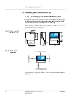


3.3 - Installing the electronics box
M2007/3en
TCT-2301 Installation instructions
33
©BTG 2004
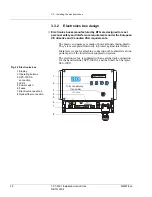
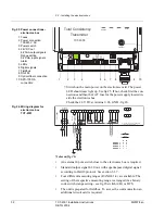
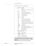
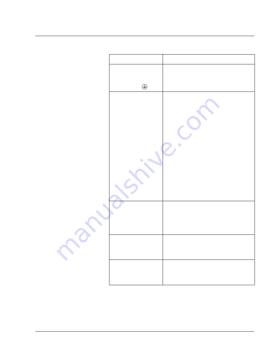
Explanation for fig 26 TCT-2301 wiring diagrams.
!
To enable communication using the Hart
®
-protocol, and use of a
hand-held terminal, a 250 min. circuit resistance is required.
A 250 resistor is connected at terminals A OUT+ and A OUT- at
the factory.
Remove the resistor when connecting the output signal.
Terminal
Function
N
Neutral
L
Phase 85-264 V AC, 47-440 Hz, power fuse 2AT
PE,
Protective earth
+24
+24V DC (to optional PCD-1000)
GND
Ground, 0V DC (to optional PCD-1000)
AOUT 1+
Output signal 4-20mA
AOUT 1-
Output signal 4-20mA
AOUT 2+
Not used
AOUT 2-
Not used
IN1
Range A for external range setting
IN2
Range B for external range setting
GND
Ground, Common for range A and B
AIN+
Input signal 0-20mA (from external equipment)
AIN-
Input signal 0-20mA (from external equipment)
ALARM+
Alarm from TCT
ALARM-
Alarm from TCT
COM +
Common (to optional PCD-1000)
DO 1
Digital output signal 1(to optional PCD-1000)
DO 2
Digital output signal 2
DI 1
Digital input signal 1
RS-485 GND
Ground
RS-485 A
Serial connection
RS-485 B
Serial connection
Fieldbus GND Ground
Fieldbus A
Fieldbus connection
Fieldbus B
Fieldbus connection
Ω
Ω


