


3.3 - Installing the electronics box
M2007/3en
TCT-2301 Installation instructions
31
©BTG 2004
3.3.5
Main power supply connections
Important:
Before installation, ensure that:
1. All power to the system has been turned off.
2. The 2AT fuses on the main card, marked F2 and F3, are in-
stalled.
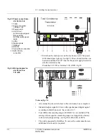
The conduit for the power supply to the electronics box should be
installed in the leftmost hole.
Wiring the main power supply screw terminal:
The earth wire must be connected to the terminal indicated by the
protective earth
symbol
PE.
See fig 26 on page 32.
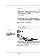
3. Strip the cable covering (insulation) to expose the shortest pos-
sible length of the connection wires.
!
Unshielded long, looped wires may cause interference! This can
interfere with the signal!
4. Once the wires are inserted, tighten the screws to secure them.
Mount the connector in its position.
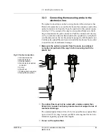
5. To ensure interference-free operation a shielded cable should be
used. Make sure the shield is correctly connected - fig 24.
6. Turn on the main power supply.
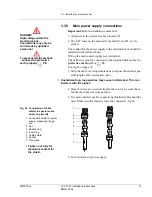
DANGER!
High voltage within the
electronics box.
Connections may only be
carried out by qualified
personnel
To prevent electrical shock
- connect the protective
earth properly
PE
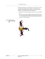
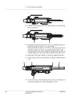
Fig 24 Connection of cable
shield, in special cable
screw cap (metal)
1 Connection cable for power
supply, measuring range
etc.
2 Nut
3 Sealing ring
4 Insert ring
5 Cable shield
6 Socket
7 Free wires
!
Tighten nut fully for
maximum contact for
the shield.
1
3
6
7
2
5
4


