


5.7 - Maintenance of the cleaning system.
M2007/3en
TCT-2301 Service instructions
109
©BTG 2004
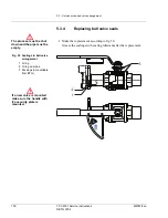
5.7 Maintenance of the cleaning system.
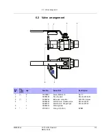
This section describes how to remove the cleaning device, with the air
cylinder, solenoid valve, water valve etc., from the pipe and disassemble
and assemble it again.
A. Removal
1. Loosen the electrical contact at the solenoid valve to move the mea-
suring probe outwards to its outer position “out of the process”.
2. Close the sluice valve.
3. Shut off air and water supply. Loosen their connections from the
transmitter.
4. Screw out the three hexagon-headed screws that join the transmitter
to the sluice valve, holding up the transmitter at the same time.
5. Loosen the fiber fitting on the electronics cabinet and pull out the fi-
ber. Protect the fiber probe with the accompanying plastic sleeve.
A. Dismantling
1. Place the transmitter in a vertical position on a workbench, with the
tip pointing downwards.
2. Loosen the air tube and the four nuts at the rear cylinder flanged end
of the transmitter.
3. Remove the rear cylinder ends, one quadratic and one cylindrical.
Then carefully pull off the outer cylinder pipe. Pull out the probe.
4. Replace the sealing and piston rings around the probe if necessary.
Check the X-ring on the rear round gable and the inner O-ring on the
front gable. Replace if necessary. Grease all sealings and O-rings
with silicone grease.
5. Check that the thin O-rings on the outer flanged end are OK and that
they are in the correct positions in their grooves. Use plenty of sili-
cone grease to help keep them in position during mounting.
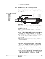
Fig 51 Sealing kit (accessory)
1 O-ring
2 O-ring
3 O-ring
4 O-ring
5 O-ring
6 O-ring
7 X-ring
8 X-ring
1
2
5
4
3
4
6
6
7
8
5
3
2


