


5.1 - Maintenance planning and quality assurance
M2007/3en
TCT-2301 Service instructions
83
©BTG 2004
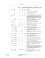
5.1.4
Functional description
A light shines through the pulp suspension from the electronics card via
the optical fiber cable. The light that passes through the suspension is
measured and analyzed. The final measuring value is then converted into
an analog output signal and shown on the display. The display also shows
the value of the analog output signal generated by the instrument.
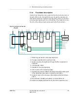
Fig 46 Electronics schematic
diagram
1. Measuring gap inserted in the pulp suspension.
2. Processor card fitted in the electronics box.
3. Optical unit where the light beam through the fiber suspension is
measured.
4. LED intensity control.
5. Amplifier for the incoming signal.
6. A/D converter of the measuring signal.
7. Digital signal processor (DSP) for handling and analysis of the signal
to the measuring value used for consistency calculation.
8. Dual port memory for exchange of data between DSP and H8 pro-
cessor.
9. Main processor handling calculations, communications etc.
10. Buttons and display positioned on the front of the electronics box.


