

4.5 - Evaluation and documentation of calibration
62
TCT-2301 Operating instructions
M2007/3en
©BTG 2004
.
.
BTG CONS. TRANSMITTTER TCT-2301
SPC software version 1.2en
Software version 1.04
Boot
version 1.01
DSP
version 7g
Date
Sign
Tag 12NT1237
Serial. no. 123456/78/90
Configuration values:
LED int
= 50.0 %
CW
= 100.0 %
DCO
= 2800
---- Range no. 1
4 mA
= 0.50 %
20 mA
= 2.00 %
Offset = 0.00 %
Damp
= 1 s
Mode
= 1
Calibration:
k0 = 0.1366
k1 = 0.8613
No. Probe cons. Lab cons. Active
1 1.52 1.66 ON
2 1.77 1.86 ON
3 1.30 1.34 ON
4 1.09 1.10 ON
5 - 0.00 OFF
6 - 0.00 OFF
7 - 0.00 OFF
8 - 0.00 OFF
9 - 0.00 OFF
Events & Alarms:
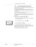
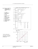
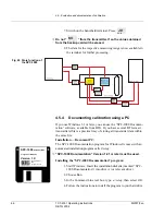
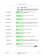
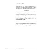
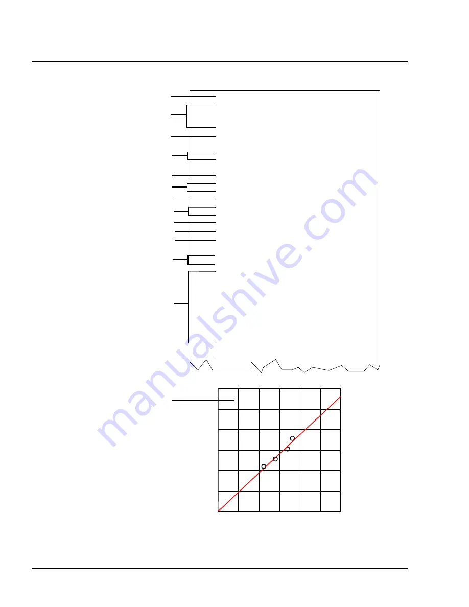
Fig 37 Sample of calibration
documentation
printout from printer
or PC
11
8
7
4
3
1
9
5
13
12
* Note: The probe signal
values shown in this diagram
diagram are not printed on a
normal printout.
15
0.00
1.00
3.00
2.00
0.00
1.00
2.00
3.00
Lab cons (%)
Probe signal (%)
14
10
6
2
1 Tx. model
2 Software version
3 Operator data
4 Tx. data
5 LED int.
6 Clear water value
7 Range
8 Measuring span
9 Consistency offset
10 Damping time
11 Mode (fiber type)
12 Calibration constants
13 Calibration data
14 Data log.


