background image

Section 06 ELECTRICAL SYSTEM

Subsection 04 (LIGHTS, GAUGE AND ACCESSORIES)

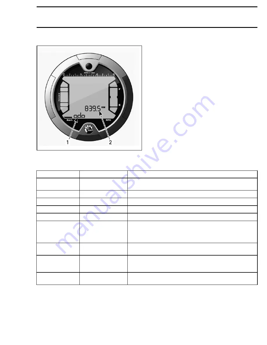
Display 3 (mode/message)

vmo2008-001-020_h

1. Display 3 (mode/message)
2. Display 2 (mode)

This display will show either an abbreviation of the
mode selected for viewing in display 2 or will com-
municate important messages to the operator if an
anomaly occurs.

Abbreviation Mode:
– ODO (odometer)
– TRIP (trip meter)
– TRIP TIME (hour meter)
– ENGINE HOURS (vehicle hour meter)
– RPM (engine revolutions per minute).

Message Mode:

MESSAGE

PILOT LIGHT(S) ON

DESCRIPTION

PARK BRAKE

Parking brake

Is displayed when parking brake is applied for more than
15 seconds (while riding).

LO BATT

Check engine

Low battery voltage, check battery voltage and charging system.

HI BATT

Check engine

High battery voltage, check battery voltage and charging system.

LOW OIL

(1)

Check engine

Engine low oil pressure, stop engine immediately.

HI TEMP

(2)

Check engine

Engine is overheating, stop engine immediately.

LIMP HOME

Check engine

Serious fault detected by the engine management that can
change the normal operation of the engine.

Check engine

indicator light will also blink, refer to

ENGINE MANAGEMENT

for

more details.

CHECK ENGINE

Check engine

Engine management fault. Check engine indicator light will also
be ON, refer to

ENGINE MANAGEMENT

for more details.

MAINTENANCE
SOON

Check engine

Periodic maintenance required.

NOTE:

To reset message, use B.U.D.S. software and click

Reset

Service

button in

Vehicle

tab.

NO ECM
COMMUNICATION

Check engine

Communication error between multifunction gauge and engine
control module (ECM). Refer to

ENGINE MANAGEMENT

.

CAUTION:

(1)

If the LOW OIL message and check engine light do not turn off right after engine

starting, stop engine. Check engine oil level. Refill if necessary. If the oil level is good, refer to the
LUBRICATION SYSTEM section.

CAUTION:

(2)

If the HIGH TEMP message and check engine light do not turn off right after engine

starting, stop engine. Refer to the COOLING SYSTEM section.

vmr2008-140

289

Summary of Contents for Outlander 400 EFI 2008

Page 1: ...y are not to be interpreted as technical drawings or exact replicas of the parts The use of BRP parts is most strongly recommended when considering replacement of any component Dealer and or distribut...

Page 2: ......

Page 3: ...scribed changes such as altitude adjustments for exam ple Owner Responsibility The owner operator is required to have engine maintenance performed to maintain emission levels within prescribed certifi...

Page 4: ...alue NOTE Always torque screws bolts and or nuts in a crisscross sequence A00A8BS Property class and head markings Property class and nut markings 5 5 8 8 10 10 12 12 4 8 4 8 4 8 8 8 8 8 8 8 9 8 9 8 9...

Page 5: ...293 800 041 on threads and allow to dry Choose proper strength Loctite threadlocker Fit bolt in the hole Apply a few drops of threadlocker at proposed tightened nut engagement area Position nut and ti...

Page 6: ...on bolt nut contact surfaces Adjusting Screw A00A3PA 1 2 1 Apply here 2 Plunger Adjust screw to proper setting Apply drops of proper strength Loctite thread locker on screw body contact surfaces Avoid...

Page 7: ...asket Allow to dry 1 or 2 minutes Apply Loctite 518 P N 293 800 038 on both sides of gasket using a clean applicator Place gasket on mating surfaces and assemble immediately NOTE If the cover is bolte...

Page 8: ...he typical construc tion of the different assemblies and in all cases may not reproduce the full detail or exact shape of the parts shown However they represent parts which have the same or a similar...

Page 9: ...elated positions TYPICAL PAGE Illustration number for publishing process Subsection title Indicates applicable models Document number for publishing process Bold face number is used to identify a part...

Page 10: ...xploded views Clean threads before applying a threadlocker Re fer to the SELF LOCKING FASTENERS and LOC TITE APPLICATION sections at the beginning of this manual for complete procedure WARNING Torque...

Page 11: ...L R ADJUST CLEAN INSPECT LUBRICATE REPLACE 200 H OR 2 YEARS OR 6000 km 3730 mi PART TASK REFER TO ENGINE Engine oil and filter R R LUBRICATION SYSTEM Valves I A I A CYLINDER HEAD CYLINDER Engine seals...

Page 12: ...ngine stop switch I I IGNITION SYSTEM and STARTING SYSTEM Lighting system HI LO intensity brake lamp headlamp aiming etc I I LIGHTS GAUGE AND ACCESSORIES CONTINUOUSLY VARIABLE TRANSMISSION CVT Drive b...

Page 13: ...0 km 3730 mi PART TASK REFER TO SUSPENSION Trailing arms I Trailing arm bearings I REAR SUSPENSION Shock absorbers I FRONT SUSPENSION and REAR SUSPENSION A arms I L Ball joints I FRONT SUSPENSION BRAK...

Page 14: ...the maintenance chart performed items in the column indicated 100 h or 1 year or 3000 km 1865 mi vmr2007 013 001_aen 1 Use this column Furthermore proceed with the following Vehicles Prepared as per S...

Page 15: ...peri od WARNING This procedure must only be performed in a well ventilated area Do not run engine dur ing storage period Proceed as follows Start the engine and allow it to run at idle speed until th...

Page 16: ...rine etc To clean the entire vehicle including metallic parts use BRP heavy duty cleaner P N 293 110 001 Inspect the vehicle and repair any damage Touch up all metal spots where paint has been scratch...

Page 17: ...ERSION ATV Submerged for a Long Time Over One Hour Disassemble engine and transmission to clean the internal parts and check if there is no rust or cor rosion on any internal parts Refer to the specif...

Page 18: ...ne reaches its operating tempera ture Stop the engine Change engine oil and filter NOTE Change oil as many times as necessary until there is no white appearance in engine oil Spray all metal parts wit...

Page 19: ...diator swelled cracked or deformed Replace radiator 8 Check condition of hoses and clamps fixation Hoses are brittle and or hard Replace Hose clamps are loose Retighten clamps 9 Check for air bubbles...

Page 20: ...lve stem seal damaged and or sealing lip is hard and or brittle Replace all valve stem seals 2 Check oil drain plug underneath engine Plug is loosen and or gasket ring is missing Retighten the plug an...

Page 21: ...cylinder head screws Screws not properly tightened Retighten screws to recommended torque and replace oil 4 Check oil for particles may indicate possible damages inside the engine Oil contamination du...

Page 22: ...gine Replace damaged gasket s and or oil seal s torque screws and refill with recommended oil up to specified level refer to TECHNICAL SPECIFICATIONS 2 Check magnetic drain plug Magnetic drain plug sh...

Page 23: ...e shift drum and damaged part s Shift fork s is are worn out and or engagement pins are damaged Replace shift fork s Shift fork s is are worn out and or fork s is are damaged Replace shift fork s Shif...

Page 24: ...oil Clean CVT system and replace damaged part s 2 Check items 1 to 4 of THE ATV ACCELERATES SLOWLY ESPECIALLY WHEN IT IS STOPPED Symptom DRIVE PULLEY NOISE AT IDLE SPEED 1 Check slider shoes drive pul...

Page 25: ...tarter ring gear condition Starter ring gear loosened Retighten ring gear and or mount it in original position balanced system 4 Check if slider shoes are present and or placed in correct position Sli...

Page 26: ...pulley surfaces Clean pulley surfaces with fine emery cloth and wipe clean using Pulley Flange Cleaner P N 413 711 809 and a cloth Drive driven pulley sheaves are damaged by stones inside CVT area Cle...

Page 27: ...SYSTEM 8 Starter starter drive or starter bushings defective or worn out Check or replace the faulty component Refer to CRANKCASE CRANKSHAFT and STARTING SYSTEM 9 Engine mechanical problem ensure tha...

Page 28: ...e and or other damages Replace repair wiring harness 4 Check magneto for damage and or electrical failure Radial position of rotor wrong due to a broken Woodruff key Replace Woodruff key Connector on...

Page 29: ...lace Fast pressure drop Verify fuel pump check valve Fails Yes OK OK Fails Fails Repair or replace Replace fuel pump module Turn ignition key ON and set engine stop switch to RUN Fuel pump does not ru...

Page 30: ...VAL INSTALLATION ENGINE REMOVAL INSTALLATION SERVICE TOOLS Description Part Number Page lifting tool 529 035 619 28 engine lifting tool 529 035 898 28 SERVICE PRODUCTS Description Part Number Page Loc...

Page 31: ...ENGINE Subsection 01 ENGINE REMOVAL INSTALLATION 48 N m 35 lbf ft Loctite 243 4 N m 35 lbf in 7 N m 62 lbf in 7 N m 62 lbf in 61 N m 45 lbf ft 25 N m 18 lbf ft 61 N m 45 lbf ft vmr2008 120 001_a 24 v...

Page 32: ...ing a pro cedure must be replaced and installed at the same location PROCEDURES ENGINE Engine Removal Place the vehicle on a workstation that will have access to an engine lifting hoist Place the tran...

Page 33: ...Remove the starter cable from the starter vmr2008 120 007_a 1 Engine ground cable 2 RED starter cable Disconnect coolant hose from cylinder head vmr2008 120 008_a 1 Coolant hose 2 Throttle body Unplug...

Page 34: ...aining the brake disc to LH drive shaft vmr2008 120 015_a 1 Brake disc screws Release parking brake and remove screws secur ing the front LH caliper vmr2008 120 014_a 1 Caliper screws Remove different...

Page 35: ...s on the frame Detach the CVT air inlet duct vmr2008 120 020_a 1 CVT air inlet duct 2 CVT cover Install the engine lifting tool P N 529 035 898 in lifting location V07C1DA TYPICAL Install the lifting...

Page 36: ...to the frame and install the rear propeller shaft Lower engine into place Install front engine support bolts Do not torque yet Install rear engine mounting bolt When installing the upper engine suppor...

Page 37: ...E Subsection 02 AIR INTAKE SYSTEM AIR INTAKE SYSTEM SERVICE PRODUCTS Description Part Number Page air filter cleaning solution 219 700 341 32 Throttle body Crankcase 1 2 N m 9 lbf in vmr2008 121 001_a...

Page 38: ...ith these components Otherwise engine performance degradation or damage can occur Remove seat and RH side panel Refer to BODY Release clamps and remove air filter housing cov er vmr2008 121 002_a Loos...

Page 39: ...air filter housing check engine oil level Oil level may be too high Inspect air filter Air Filter Housing Removal Remove seat and console Refer to BODY On RH side of vehicle perform the following Remo...

Page 40: ...EFI Outlander 400 EFI XT NEW 3 5 N m 31 lbf in NEW 13 N m 115 lbf in 10 N m 89 lbf in 6 N m 53 lbf in 3 5 N m 31 lbf in 3 5 N m 31 lbf in NEW 13 N m 115 lbf in 10 N m 89 lbf in 6 N m 53 lbf in 25 N m...

Page 41: ...must strictly be adhered to Locking devices e g locking tabs elastic stop nuts self locking fasteners cotter pin etc must be replaced with new ones Always inspect exhaust system parts for the fol lowi...

Page 42: ...correctly to prevent leakage Install muffler bolt Use the following illustration to position parts properly vmr2008 122 008_a 1 Spacer MAX Series only 2 Flat washer M8 3 Muffler 4 Large washer 5 Muff...

Page 43: ...xhaust Pipe Installation Install a NEW exhaust gasket on exhaust pipe end cylinder head side Secure exhaust pipe on cylinder head with ex haust nuts Do not tighten yet Install muffler Align all parts...

Page 44: ...Description Part Number Page Loctite 243 blue 293 800 060 43 44 Molykote PG 54 420 899 763 41 8 N m 71 lbf in 15 1 2 Molykote Pg 54 Molykote Pg 54 Molykote Pg 54 3 5 6 4 14 6 5 N m 58 lbf in 25 N m 1...

Page 45: ...of a locking device is impaired it must be renewed PROCEDURES REWIND STARTER Rewind Starter Removal Remove engine cover vmr2008 123 100_a Remove rewind starter mounting bolts no 15 and pull rewind sta...

Page 46: ...ttention to the following details WARNING Always install new spring into starter hous ing Torsion spring is spring loaded so handle with care during installation Always wear safety goggles and hand gl...

Page 47: ...hub notch engages in the rewind spring hook WARNING To prevent spring from flying out of the guide it is mandatory to secure rope sheave in place Always handle with care and use safety goggles and han...

Page 48: ...00motr228A TYPICAL 1 Fuse end of starter rope Pass rope through starter grip tie a knot in the rope end R400motr230A TYPICAL Insert rope end down and pull the starter grip over the knot Rewind Starter...

Page 49: ...ng pulley no 14 from crankshaft MAG side Starting Pulley Installation For installation reverse the removal procedure Pay attention to the following details CAUTION Take care to have the starting pulle...

Page 50: ...SERVICE TOOLS Description Part Number Page adapter hose 529 035 652 50 pressure gauge 529 035 709 50 SERVICE PRODUCTS Description Part Number Page XP S 5W30 4 stroke oil 219 700 706 47 XP S 5W40 synth...

Page 51: ...SYSTEM M18 x 1 5 10 N m 89 lbf in NEW Loctite 243 NEW NEW 12 N m 106 lbf in Engine oil Engine oil 2 1 Engine oil 13 Engine oil 7 8 9 12 11 6 30 N m 22 lbf ft 4 3 10 N m 89 lbf in 5 10 N m 89 lbf in En...

Page 52: ...vice label certification on the oil container it must con tain at least one of the above standards The XP S 5W30 4 stroke oil P N 219 700 706 is recommended For improved overall performance and all se...

Page 53: ...en gine oil is warm Place a drain pan under the engine drain plug area Clean the drain plug area Remove dipstick CAUTION Pay attention not to lose the O ring on dipstick vmr2008 124 101_a 1 Dipstick 2...

Page 54: ...oil filter inlet and outlet area for dirt and other contaminations 2 R400motr112A 1 1 Inlet bore from the oil pump to the oil filter 2 Outlet bore to the engine oil providing system Oil Filter Instal...

Page 55: ...il pressure as per fol lowing table The engine oil pressure should be within the fol lowing values PRESSION RPM 1300 RPM 6000 RPM Minimal 70 kPa 10 PSI 350 kPa 51 PSI Nominal 350 kPa 51 PSI 500 kPa 73...

Page 56: ...n OPS CONNECTOR ENGINE NOT RUNNING ENGINE RUNNING PIN RESISTANCE 1 Engine ground Close to 0 normally closed switch Infinitely high when pressure reaches 30 60 kPa 4 4 8 7 PSI vmr2008 124 104_a If resi...

Page 57: ...r ring on the oil strainer cover If O ring and or rubber ring is are brittle cracked or hard replace the defective part s Clean both contact surfaces of oil strainer cover Check and clean the oil inle...

Page 58: ...t valve piston for scoring or other damages Check compression spring for free length COMPRESSION SPRING FREE LENGTH NEW NOMINAL 64 mm 2 519 in SERVICE LIMIT 62 mm 2 441 in Replace both parts if import...

Page 59: ...pump shaft assembly will be easier to remove CAUTION Pay attention not to drop the dowel pins inside the engine 1 R400motr120A 1 Oil pump system 1 vmr2006 054 004 1 Dowel pins Remove oil pump gear no...

Page 60: ...assembly Check the inside of oil pump housing and its cover for scoring or other damages If so change the complete oil pump assembly 1 R400motr126A 1 Pittings on the teeth Using a feeler gauge measur...

Page 61: ...il pressure de creases Oil Pump Installation For installation reverse the removal procedure CAUTION Never apply any sealing compound on split surfaces of oil pump Tightening oil pump housing screws as...

Page 62: ...00 64 large hose pincher 529 032 500 62 oil seal pusher 529 035 757 75 water pump ceramic seal installer 529 035 766 75 Fluke 115 multimeter 529 035 868 69 test cap 529 035 991 64 ECM adapter tool 529...

Page 63: ...Section 03 ENGINE Subsection 06 COOLING SYSTEM RADIATOR 2008 5 5 N m 49 lbf in 7 N m 62 lbf in 7 N m 62 lbf in Some 2008 Models vmr2008 125 001_a 58 vmr2008 125...

Page 64: ...Section 03 ENGINE Subsection 06 COOLING SYSTEM RADIATOR 2009 5 5 N m 49 lbf in 7 N m 62 lbf in vmr2008 125 011_a vmr2008 125 59...

Page 65: ...Section 03 ENGINE Subsection 06 COOLING SYSTEM WATER PUMP 2 10 N m 89 lbf in 1 5 2 5 N m 22 lbf in Right hand thread Engine oil Super Lube grease 4 3 vmr2007 024 001_b 60 vmr2008 125...

Page 66: ...Section 03 ENGINE Subsection 06 COOLING SYSTEM THERMOSTAT 5 N m 44 lbf in 6 N m 53 lbf in 16 N m 142 lbf in Loctite 243 vmr2008 125 002_a vmr2008 125 61...

Page 67: ...pletely flushed and refilled CAUTION To prevent rust formation or freez ing conditions always replenish the system with an ethylene glycol antifreeze containing corrosion inhibitors specifically recom...

Page 68: ...asket ring 2 Bleeder screw Remove hose pincher from radiator coolant return hose Top up radiator coolant and install radiator cap Refill coolant tank up to the MIN level mark and install the coolant t...

Page 69: ...se Using pressure vacuum pump P N 529 021 800 pressurize system to 103 kPa 15 PSI 1 V07C0NA TYPICAL 1 Special radiator cap Check all hoses radiator and engine cylinder base for coolant leaks or air bu...

Page 70: ...thermostat should open when the wa ter temperature reaches 65 C 149 F Thermostat Installation For installation reverse the removal procedure pay attention to the following details Check gasket to see...

Page 71: ...V07C0PA 1 Radiator coolant return hose 1 V07C0QA TYPICAL 1 Radiator coolant outlet hose Remove overflow hose at radiator filler neck vmr2008 125 013_a TYPICAL 1 Radiator overflow hose 2 Spring clamp D...

Page 72: ...vent overflow hose in the coolant tank cap allows excess pressure and coolant to escape When the system cools and the pressure decreas es generally after engine shutdown the internal system pressure...

Page 73: ...ed down and away from moving parts electrical components or any component that may be adversely affected by overflowing coolant RADIATOR COOLING FAN Radiator Cooling Fan Test NOTE It is not required t...

Page 74: ...115 multimeter P N 529 035 868 to Vdc and test fan relay input voltage as per fol lowing table FAN RELAY INPUT VOLTAGE TEST TEST PROBES READING Contact 1D fuse box Contact 3D fuse box Chassis ground B...

Page 75: ...wiring connector as required If cooling fan relay relay input voltage and relay control circuit continuity tested good the problem is related to the ECM Refer to the ELECTRONIC FUEL INJECTION section...

Page 76: ...POWER CIRCUIT CONTINUITY TEST FUSE BOX CONTACTS FAN CONNECTOR RESISTANCE 20 C 68 F 3E 9C 8C Pin B BR WH Close to 0 Repair or replace wiring connectors as required Radiator Cooling Fan Removal Remove b...

Page 77: ...e fan vent tube on 2009 models COOLANT TEMPERATURE SENSOR CTS The coolant temperature sensor is located next to the thermostat housing on the RH rear side of the cylinder head vmr2008 125 003_b 1 Cool...

Page 78: ...er as per previous proce dure Unscrew impeller from water pump shaft 1 R400motr140A 1 Impeller NOTE Water pump shaft and impeller have right hand threads Remove by turning counterclock wise and instal...

Page 79: ...the shaft and rotary seal out of the magneto cover CAUTION Always replace rotary seal and wa ter pump shaft no 5 together Also install a new oil seal no 3 at the same time 1 R400motr144A 1 Water pump...

Page 80: ...oil seal no 3 using oil seal pusher P N 529 035 757 vmr2006 040 015_a 1 Handle 2 Pusher 1 R400motr147A 3 2 1 Oil seal for water pump shaft 2 Oil seal pusher 3 Handle for insertion jig Use water pump...

Page 81: ...48A TYPICAL 1 Water pump shaft with rotary seal 2 Water pump ceramic seal installer Always use torque values specified in the explod ed view Torque water pump cover screws as per sequence specified in...

Page 82: ...puller 529 035 748 86 oil seal installer 529 035 759 82 Fluke 111 multimeter 529 035 868 82 84 87 oil seal protector 529 035 935 80 82 SERVICE PRODUCTS Description Part Number Page dielectric grease...

Page 83: ...89 lbf in 10 N m 89 lbf in 10 N m 89 lbf in 10 N m 89 lbf in 25 N m 18 lbf ft 25 N m 18 lbf ft Loctite 5910 Loctite 5910 Loctite 243 180 N m 133 lbf ft Super Lube grease Super Lube grease Loctite 243...

Page 84: ...cified If the efficiency of a locking device is impaired it must be re newed PROCEDURES MAGNETO COVER Magneto Cover Removal Remove engine from vehicle Remove 4WD coupling unit Lock crankshaft at TDC r...

Page 85: ...minutes It is suggested to have all you need on hand to save time Use a plexyglass plate and apply some sealant on it Use a soft rubber roller 50 75 mm 2 3 in as per supplier available in arts produc...

Page 86: ...is as per following illustration vmr2008 126 004_b Let the sealant dry before starting engine Refer to the manufacturer s label for the sealant curing time OIL SEAL Remove rewind starter refer to REW...

Page 87: ...ther removed parts in the reverse order Install magneto cover refer to MAGNETO COVER above Without Magneto Cover Removed Using a suitable tube with the proper diameter install the oil seal as per foll...

Page 88: ...s table vmr2008 138 007_a STATOR CONNECTOR PIN OUT NOTE Pin 2 is not used If resistance readings are as specified repair or re place connector or wiring between the front stator connector and the volt...

Page 89: ...readings are not as specified the sta tor or the wiring is shorted to ground and needs to be repaired or replaced Reinstall removed connectors and panels Stator Output Voltage Test Test at Voltage Re...

Page 90: ...or Install removed connectors and panels Stator Removal Remove Magneto cover Stator screws Holding strip screw Stator vmr2008 126 006_a 1 Stator 2 Stator screws 3 Holding strip 4 Holding strip screw S...

Page 91: ...r otherwise damaged Measure trigger wheel teeth diameter at different locations Maximum allowed diameter is 134 mm 5 28 in Otherwise check for bent teeth vmr2008 014 011_a 1 Rotor 2 Trigger wheel 3 Ma...

Page 92: ...39 004_c FUSE F3 NOTE Check engine will be displayed in multi function gauge starter will crank engine but with an initial delay of approximately 4 seconds Remove RH side panel refer to BODY section P...

Page 93: ...at tributable to loose dirty or corroded connections STARTER CABLE CONTINUITY TEST RED PROBE BLACK PROBE MEASUREMENT Starter terminal Solenoid starter terminal Close to 0 continuity vmr2008 139 009_c...

Page 94: ...013_a Apply Super Lube grease P N 293 550 030 to the starter O ring seal vmr2008 139 014_a Torque starter screws to 10 N m 89 lbf in Connect the RED cable to the starter and torque nut to 6 N m 53 lbf...

Page 95: ...Part Number Page pulley holding tool 529 006 400 95 104 drive pulley puller 529 035 746 96 driven pulley expander 529 035 747 94 pulley holding tool 529 035 771 104 SERVICE PRODUCTS Description Part...

Page 96: ...MISSION CVT 1 100 N m 74 lbf ft Loctite 767 antiseize lubricant 7 N m 62 lbf in 60 N m 44 lbf ft 5 N m 44 lbf in 2 3 4 5 6 8 12 13 15 14 13 16 11 10 9 7 Pulley flange cleaner Isoflex topas NB52 LH thr...

Page 97: ...is impaired it must be re newed WARNING Never touch CVT while engine is running Never drive vehicle when CVT cover is re moved WARNING Any drive pulley repairs must be performed by an authorized Can A...

Page 98: ...rew in of driven pulley expander 2 Removal direction for belt Drive Belt Inspection Inspect belt for cracks fraying or abnormal wear Replace if necessary Check drive belt width at cord level Replace i...

Page 99: ...ove and remove excessive Loctite Install cover with gasket imme diately Install the center top screw of cover in first vmr2008 127 002_b 1 Install first Install the other screws then torque them in a...

Page 100: ...1 Mark on drive pulley sliding sheave 2 Mark on governor cup Unscrew drive pulley screw clockwise CAUTION Drive pulley screw has LH threads Remove screw spring washer and thrust washer 4 R400motr162C...

Page 101: ...lider shoes out of each bearing sleeve Use a flat screwdriver if necessary 1 R400motr171A 1 Slider shoe Put governor cup on a vise Use protection plates on the vise jaws to avoid marks and or damages...

Page 102: ...f of spring sleeves are visible 2 R400motr166A 4 1 3 1 One way clutch 2 Fixed sheave 3 Spring sleeve area 4 Direction of removal Hold both spring sleeves with fingers when pulling out the one way clut...

Page 103: ...f external diam eter NOTE Replace governor cup if the roller does not move freely Measure the roller diameter If one roller is out of specification replace all rollers ROLLER OUTER DIAMETER NOMINAL 13...

Page 104: ...ing sheave no 1 for cracks and sliding contact surface for excessive wear Replace slid ing sheave if necessary Measure centrifugal lever pivot bolt bores Re place sliding sheave if bores are out of sp...

Page 105: ...coring and other damages If so re place fixed sheave 1 R400motr175A 1 Visually check here Check for any marks on fixed sheave plate Re place if necessary Check ring gear teeth for excessive wear or ot...

Page 106: ...embly reverse the disassembly procedure Pay attention to following details One Way Clutch Apply Isoflex grease Topas NB 52 P N 293 550 021 on spring sleeves no 8 and their springs then between one way...

Page 107: ...Rollers must move easily after in stallation Insert slider shoes no 3 into governor cup to prop erly slide in guides Align governor cup with sliding sheave using the marks traced at disassembly 2 R400...

Page 108: ...d torque screw counterclockwise to 100 N m 74 lbf ft 529 006 400 NOTE Drive pulley screw has LH threads 1 R400motr177A 2 1 Pulley holding tool 2 Drive pulley removal installation area DRIVEN PULLEY Dr...

Page 109: ...e driven pulley and hold in this position while removing screw and washer WARNING Driven pulley is spring loaded Hold driven clutch pulley tight and slowly remove the driven pulley screw to release sp...

Page 110: ...ne steel wool and dry cloth Use pulley flange cleaner P N 413 711 809 to clean driven pulley Clean the CVT crankcase area from contamination Using a paper towel with cleaning solvent to clean main sha...

Page 111: ...METER NOMINAL 30 060 to 30 100 mm 1 183 to 1 185 in SERVICE LIMIT 30 200 mm 1 189 in Check torque gear for visible damage and wear limit with a caliper A R400motr184A B A Measurement inside B Measurem...

Page 112: ...attention to following details Heat ball bearing area up to 100 C 212 F before ball bearing installation NOTE Place new ball bearing in a freezer for 10 minutes before installation Install ball bearin...

Page 113: ...sleeve 3 Chamfered area of distance sleeve Install cam retainer on main shaft end the right way then install cam NOTE Place cam retainer with printed mark EN GINE SIDE towards the engine 2 R400motr19...

Page 114: ...Section 03 ENGINE Subsection 08 CONTINUOUSLY VARIABLE TRANSMISSION CVT 2 R400motr193A 1 1 Washer 2 Driven pulley screw NOTE Driven pulley end play is 0 zero Torque driven pulley screw 110 vmr2008 127...

Page 115: ...tool 529 035 919 133 piston circlip installer 529 035 921 136 valve guide remover 529 035 924 131 camshaft locking tool 529 035 926 120 132 valve guide installer 529 036 140 131 SERVICE TOOLS OTHER SU...

Page 116: ...n Loctite 243 Loctite 767 antiseize lubricant Engine oil Loctite 243 Loctite 243 1 2 14 11 12 13 19 18 20 30 31 29 33 22 34 32 7 5 6 4 9 10 24 26 28 16 17 19 18 21 30 31 29 33 34 22 15 27 23 10 N m 89...

Page 117: ...Section 03 ENGINE Subsection 09 CYLINDER HEAD CYLINDER CYLINDER AND PISTON NEW 20 N m 15 lbf ft 60 8 7 3 Engine oil 4 6 Engine oil Engine oil R400motr16T vmr2008 128 113...

Page 118: ...to keep them as a group If you find a de fective component it would be much easier to find the cause of the failure among its group of parts e g you found a worn valve guide A bent spring could be the...

Page 119: ...k plug 1 R400motr104A 2 1 Spark plug cable 2 Spark plug Remove valve cover Refer to CYLINDER HEAD CYLINDER vmr2008_128 003_a 1 Valve cover screws 2 Valve cover 3 Valve cover gasket Turn crankshaft unt...

Page 120: ...chamber with air pressure Note the amount of leaking or percentage de pending on tester LEAKAGE PERCENTAGE ENGINE CONDITION 0 to 15 Excellent condition 16 to 25 Good condition 26 to 40 Fair condition...

Page 121: ...gasket vmr2008_128 005_a 1 Valve cover 2 Gasket Valve Cover Inspection Check the gasket no 1 on the valve cover no 2 if it is brittle cracked or hard If so replace the gasket Valve Cover Installation...

Page 122: ...place them together 2 1 R400motr59B 3 1 Centrifugal weight 2 Edge of centrifugal weight 3 Bearing bore Decompressor Installation The installation is the reverse of the removal pro cedure but pay atten...

Page 123: ...1 1 Chain tensioner screw 2 Chain tensioner housing Tensioner Inspection Check chain tensioner plunger no 4 for free movement and or scoring Check if possible chain guides for wear Replace as necessa...

Page 124: ...tighten the plug screw to 4 5 N m 40 lbf in CAMSHAFT TIMING GEAR Camshaft Timing Gear Removal Remove Valve cover Chain tensioner Using the camshaft locking tool P N 529 035 926 lock the camshaft at T...

Page 125: ...be locked on TDC position to place camshaft tim ing gear and timing chain in the proper posi tion Never use the mark on the magneto to find the TDC Only use the crankshaft locking tool to locate the T...

Page 126: ...TDC compression refer to CRANKCASE CRANKSHAFT section and CAMSHAFT TIMING GEAR in this section Install timing chain then adjust chain tension re fer to TIMING CHAIN TENSIONER in this section CAUTION...

Page 127: ...00motr67A 4 1 1 3 1 2 thrust washers 2 Rocker arm exhaust side 3 Cylinder head spark plug side 4 Big taper to PTO side Rocker Arm Inspection Inspect each rocker arm for cracks and scored fric tion sur...

Page 128: ...m shafts with the chamfered edge first and use following procedure Insert a rocker arm shaft through rocker arm shaft bore Install thrust washer no 19 then the proper rocker arm exhaust no 20 or intak...

Page 129: ...easure camshaft bearing journal diameter and lobe height using a micrometer C R400motr76A A B D A Camshaft lobe exhaust valves B Camshaft lobe intake valves C Camshaft journal MAG side D Camshaft jour...

Page 130: ...slot vmr2008_128 106_b 1 Camshaft retaining plate position 2 Slot retaining camshaft 3 Direction of movement For other parts refer to proper installation proce dure CYLINDER HEAD Cylinder Head Removal...

Page 131: ...es Clean oil support through the cylinder head from contamination vmr2008_128 107_a 1 Oil port to lubricate camshaft lobes intake exhaust 2 Oil supply to camshaft bearing journal MAG side 3 Oil supply...

Page 132: ...r cup P N 529 035 725 vmr2006 043 019 vmr2006 043 020 WARNING Always wear safety glasses when disassem bling valve springs Be careful when unlock ing valves Components could fly away be cause of the s...

Page 133: ...2 Valve cotters After spring is installed ensure it is properly locked by tapping on valve stem end with a soft hammer so that valve opens and closes a few times CAUTION An improperly locked valve sp...

Page 134: ...valve guide no 32 if it is out of specifica tion or has other damages such as wear or friction surface VALVE GUIDE DIAMETER intake and exhaust valves SERVICE LIMIT 5 050 mm 1988 in Valve Face and Seat...

Page 135: ...a soft hammer so that valve opens and closes a few times CAUTION An improperly locked valve spring will cause engine damage VALVE GUIDE Valve Guide Removal Remove Cylinder head Valve spring Valves NO...

Page 136: ...s seat with a lapping tool A R400motr89A 1 2 3 1 Valve seat 2 Valve face contact surface to valve seat 3 Turn valve while pushing against cylinder head A Valve seat angle 45 NOTE Ensure to seat valves...

Page 137: ...m 1 260 in CYLINDER TAPER NEW 0 038 mm 0015 in SERVICE LIMIT 0 090 mm 0035 in Distance between measurements should not ex ceed the service limit mentioned above Cylinder Out of Round Measure cylinder...

Page 138: ...in the timing chain area WARNING Piston circlips are spring loaded Remove one piston circlip and discard it 1 R400motr94A 1 Piston circlip NOTE The removal of both piston circlips is not necessary to...

Page 139: ...0 zero Position the dial bore gauge 20 mm 787 in above cylinder base measuring perpendicularly 90 to piston pin axis Read the measurement on the cylinder bore gauge The result is the exact piston cyli...

Page 140: ...ion For installation reverse the removal procedure Pay attention to the following details Apply engine oil on the piston pin Place piston no 37 over connecting rod Position the piston with the punched...

Page 141: ...030 to 0 070 mm 0012 to 0028 in SERVICE LIMIT 0 150 mm 0059 in LOWER COMPRESSION RING NEW 0 020 to 0 060 mm 0008 to 0024 in SERVICE LIMIT 0 150 mm 0059 in OIL SCRAPER RING NEW 0 010 to 0 180 mm 0004...

Page 142: ...n ring 2 Lower compression ring 3 Oil scraper ring CAUTION Ensure that top and second rings are not interchanged NOTE Use a ring expander to prevent breakage during installation The oil ring must be i...

Page 143: ...bearing remover 529 035 756 151 oil seal installer 529 035 760 144 oil seal installer 529 035 761 143 needle bearing installer 529 035 762 150 needle bearing installer 529 035 763 150 crankcase suppo...

Page 144: ...Loctite 5910 17 18 21 15 16 20 T1 T1 T2 T1 T2 T2 T2 Multi purpose grease Engine oil 10 12 13 14 2 9 T1 T1 Loctite 5910 Multi purpose grease 5 T2 12 Engine oil NEW NEW 11 T2 Multi purpose grease Locti...

Page 145: ...Section 03 ENGINE Subsection 10 CRANKCASE CRANKSHAFT CRANKSHAFT BALANCER SHAFT NEW 20 N m 15 lbf ft 60 8 7 3 Engine oil 4 6 Engine oil Engine oil R400motr16T vmr2008 129 141...

Page 146: ...it must be renewed PROCEDURES STARTER DRIVE Starter Drive Removal Remove drive pulley refer to CONTINUOUSLY VARIABLE TRANSMISSION Remove screws retaining starter drive cover NOTE Do not lose shims and...

Page 147: ...oves Re place bearing flange if necessary Output Shaft Oil Seal Installation Use the oil seal installer P N 529 035 941 and insertion handle P N 420 877 650 for installation of the oil seal vmr2008 12...

Page 148: ...with the proper diameter install the seal Align the previous scribing marks and install the shifting plate Torque shifting plate bolt to 10 N m 89 lbf in CRANKSHAFT OIL SEAL Crankshaft Oil Seal Remova...

Page 149: ...EARBOX OUTPUT SHAFT Cylinder head and cylinder refer to CYLINDER HEAD CYLINDER Drive and driven pulley refer to CONTINUOUS LY VARIABLE TRANSMISSION Measure axial clearance between the crankshaft and c...

Page 150: ...n one direction then make the final brushing perpendicularly 90 to the first pass cross hatch CAUTION Do not wipe with rags Use a new clean hand towel only Crankcase Inspection NOTE To check some part...

Page 151: ...ily with a flat screwdriver CAUTION Avoid scoring bearing seat or oil seal bore in crankcase Balancer Shaft Oil Seal Installation CAUTION Oil seal must be installed with seal ing lip towards balancer...

Page 152: ...ase support PTO 2 Crankcase PTO side 2 1 R400motr45A 3 PUSH PLAIN BEARINGS OUTSIDE 1 Plain bearing remover installer 2 Plain bearing 3 Crankcase PTO Crankshaft Plain Bearing Installation To install th...

Page 153: ...icular axle to cylinder base 4 Crankcase MAG 1 R400motr42B 2 3 4 1 Mark on crankcase and oil bore position 2 Split between bearing halves 3 Perpendicular axle to cylinder base 4 Crankcase PTO CAUTION...

Page 154: ...le R400motr203A 3 2 1 BEVEL GEAR 1 Bevel gear needle bearing 2 Needle bearing installer 3 Installer handle Counter Shaft Needle Bearing Removal To remove counter shaft needle bearing no 19 use a punch...

Page 155: ...ion handle P N 420 877 650 vmr2008 126 010_a 1 Needle bearing installer 2 Handle 1 R400motr241A 2 STARTER DRIVE PINION 1 Starter drive needle bearing PTO side 2 Needle bearing installer Balancer Shaft...

Page 156: ...u need on hand to save time Use a plexiglas plate and apply some sealant on it Use a soft rubber roller 50 75 mm 2 3 in available in arts products suppliers for printmak ing and roll the sealant to ge...

Page 157: ...on to following detail Align the dot on crankshaft gear with the balancer shaft gear dot 1 R400motr25A 1 Punched marks located in the gears CRANKSHAFT Crankshaft Locking Procedure Unplug spark plug ca...

Page 158: ...400motr235A 1 Screwdriver Lock crankshaft with the crankshaft locking bolt P N 529 035 617 vmr2006 043 013 R400motr236A 1 2 1 Crankshaft locking bolt 2 Front output shaft area Crankshaft Removal Remov...

Page 159: ...400motr30A A Piston pin diameter in the area of the plain bearing CONNECTING ROD SMALL END DIAMETER NEW 20 010 to 20 020 mm 7878 to 7882 in SERVICE LIMIT 20 060 mm 7898 in PISTON PIN DIAMETER NEW 19 9...

Page 160: ...ed initially Do the torque procedure as described further R400motr33A A A Connecting rod big end plain bearing CRANKSHAFT PIN DIAMETER NEW 40 009 to 40 025 mm 1 575 to 1 576 in SERVICE LIMIT 39 980 mm...

Page 161: ...e connecting rod 3 Nose of bearing in line with connecting rod groove CAUTION Always use NEW connecting rod screws for the final assembly of the crankshaft Torque NEW connecting rod screws no 7 as per...

Page 162: ...ase and crankshaft thrust surface Install the crankshaft locking bolt P N 529 035 617 to keep the crankshaft in TDC position be fore installing the camshaft timing chain refer to CRANKSHAFT LOCKING PR...

Page 163: ...OUTPUT SHAFT Engine oil 8 11 10 6 7 9 Engine oil Engine oil 35 36 13 38 31 30 Engine oil 33 32 29 Loctite 243 10 N m 89 lbf in 22 20 Engine oil 34 12 14 18 Engine oil 27 23 21 25 28 17 Engine oil 15 E...

Page 164: ...al clearance prior to re move it 1 R400motr195A 2 1 Output shaft 2 Dial indicator OUTPUT SHAFT AXIAL CLEARANCE SERVICE LIMIT 0 30 mm 012 in If the output shaft axial clearance is out of specifi cation...

Page 165: ...e hard or damaged Clean crankcase and magneto cover mating sur face and especially the bearing areas from metal particles or other contamination Output Shaft Installation For installation reverse the...

Page 166: ...n the above table Install output shaft and output shaft bearing cover Install magneto cover Refer to MAGNE TO STARTER section in this manual for proce dure GEARBOX Gearbox Disassembly Remove engine fr...

Page 167: ...ver in the slot of index lever Turn screwdriver counterclockwise and remove shift drum 1 R400trans18A 2 1 Index lever 2 Shift drum Remove Shift fork no 12 Bevel gear shaft no 13 with low range gear as...

Page 168: ...replace bearing Gears Check tooth flanks of gears Replace gears only together with the correspond ing meshing gears NOTE Always replace circlips and use special pli ers to install them Measure the eng...

Page 169: ...shift fork claw thickness SHIFT FORK CLAW THICKNESS NEW 4 800 to 4 860 mm 189 to 191 in SERVICE LIMIT 4 750 mm 187 in 1 R400trans19A A 1 Micrometer A Shift fork claw thickness Thrust Washers Check th...

Page 170: ...the proper thrust washer thickness E as per following illustration The bevel gear axial clearance is adjusted by find ing the proper thrust washer thickness J as per following illustration NOTE Clean...

Page 171: ...in the MAG side and the mating surface of crankcase magneto cover 1 R400trans25A 2 1 Depth gauge 2 Washer thrust surface A 2 mm 0787 in nominal thickness of axial needle bearing no 36 When all the mea...

Page 172: ...ourse of calculation to deter mine the theoretical thickness I of thrust washer no 23 on PTO side crankcase I F G H A E F Distance between mating surface crankcase PTO to ball bearing inner race 2 R40...

Page 173: ...resents a value equal at 1 40 mm 0551 in Gearbox Assembly For assembly reverse the disassembly procedure Pay attention to the following details Install Intermediate gear shaft no 28 needle bearing no...

Page 174: ...stance sleeve no 16 on main shaft end PTO side CAUTION Place O ring including distance sleeve right away Chamfered bore of distance sleeve has to face the engine 2 R400motr215A 1 3 1 O ring 2 Distance...

Page 175: ...g Refer to AIR INTAKE SYSTEM Unplug gearbox position switch connector vmr2008 129 051_a Use a multimeter and set it to Set vehicle shifter in the position to test P R N Measure the resistance of the p...

Page 176: ...tch Gearbox Position Switch Installation For installation reverse the removal procedure Pay attention to the following details Take care not to damage gearbox position switch es threads during install...

Page 177: ...ber Page XP S synthetic grease 293 550 010 175 Loctite 243 blue 293 800 060 174 24 N m 18 lbf ft Loctite 243 15 N m 133 lbf in XP S synthetic grease 10 N m 89 lbf in 10 N m 89 lbf in 10 N m 89 lbf in...

Page 178: ...ne where specified If the efficiency of a locking device is impaired it must be re newed PROCEDURES HANDLE Handle Removal Loosen the nut under shift lever handle vmr2007 040 002_a 1 Shift lever handle...

Page 179: ...te Remove the link rod Link Rod Inspection Check the link rod for bending or cracks Check the tie rod at the end of link rod Replace the link rod if necessary Check both O rings on threaded fitting an...

Page 180: ...a 1 Shifting plate bolt Mark the location of shifting plate before removing it from shift shaft vmr2007 040 009_b 1 Mark aligned with slot Remove the shifting plate Shifting Plate Inspection Check shi...

Page 181: ...tion 12 SHIFTER vmr2007 040 009_b 1 Mark aligned with slot Install the shifting plate bolt Install link rod and adjust it refer to LINK ROD above Install side panel and check if the shifting system wo...

Page 182: ...N COIL INJECTOR CTS CPS TPS Throttle Position Sensor MAPTS Manifold Absolute Pressure and Temperature Sensor CTS Coolant Temperature Sensor OPS Oil Pressure Switch CPS Crankshaft Position Sensor GBPS...

Page 183: ...ECM Ignition coil Fuel injector Tail brake light Multifunction gauge Start switch Starter solenoid Diagnostic connector Light switch Actuator switch 2wd 4wd Winch switches Power outlet Cooling fan re...

Page 184: ...CTS OPS CPS IDLE AIR CONTROL VALVE OVERRIDE SWITCH BRAKE SWITCH GBPS BE GN WH BE Diagnostic connector VFB ECM FUEL LEVEL SENSOR 2WD 4WD ACTUATOR SWITCH CPS Crankshaft Position Sensor CTS Coolant Temp...

Page 185: ...ARE BE GN WK BE MFG DC Beige Green White Beige Multifunction gauge Diagnostic connector ECM Engine control module MFG ECM C1 B1 1 2 WH BE WH BE BE GN DC BE GN 19 4 vmr2008 132 007_aen ENGINE CONTROL M...

Page 186: ...e performance reduced modes allow the rid er to go back home which would not be otherwise possible without this advanced system Refer to the MONITORING SYSTEM FAULT CODES Diagnostic Mode The ECM featu...

Page 187: ...400 EFI available on BOSSWeb MPI 2 P N 529 036 018 Optional extension cable P N 529 035 697 Diagnostic cable P N 710 000 851 MPI 2 Power Supply The MPI 2 uses the PC computer USB port for for its powe...

Page 188: ...nspection to diagnose and monitor components and to carry out settings such as the closed throt tle and idle actuator For more information pertaining to the use of the B U D S software use its help wh...

Page 189: ...otective cap to minimize the possibility of communication error Changes in ECM Anytime a change is brought in ECM through B U D S there will be an EMS Tracking mes sage that will say Remove key from v...

Page 190: ...y fuel cut off TPS or internal memory error 5000 High battery voltage 7000 The following components or functions are moni tored COMPONENT EMS TPS CPS MAPTS CTS OPS IACV GBPS ignition coil and fuel inj...

Page 191: ...ultifunction gauge can display only fault codes that are active Occured non active faults can only be seen using B U D S Proceed as follows Turn ignition key to lights ON position vmr2008 134 001 Use...

Page 192: ...ion vmr2008 134 003_d NOTE To quickly exit the on board diagnostic mode press and HOLD the mode button SPECIFIC FAULT CODES TPS Throttle Position Sensor Faults Faults which are reported in B U D S fal...

Page 193: ...d TPS closed position not reset Reset Closed Throttle and Idle Actuator Throttle body has been replaced and TPS closed position not reset Reset Closed Throttle and Idle Actuator ECM has been replaced...

Page 194: ...r approximately 2511 ohms at 20 C Replace the sensor if necessary Check circuits between Sensor pin 2 and ECM pin F3 between C3 1 and between A1 3 114 Manifold temperature sensor signal switched inter...

Page 195: ...M to the relay shorted to a GND Check for damaged or disconnected fuel pump relay damaged circuit wires damaged connectors or damaged ECM output pins Check circuit from relay pin 1B to ECM pin J1 232...

Page 196: ...x 260 ohm Check CPS AC voltage value approx 1 V Check CPS wires Check if CPS is dirty with metal particle Check encoder wheel 351 Ignition coil signal shorted to Battery 12 V Faulty primary ignition c...

Page 197: ...voltage input Battery voltage too high faulty voltage regulator faulty magneto Check battery voltage for 13 8 to 15 0 volts with engine idling Replace voltage regulator if necessary 600 CAN communica...

Page 198: ...isconnected Faulty injector cut wires faulty terminals Check ignition fuse Check for approximately 12 2 ohms on injector Check circuit between Injector pin 1 and ECM L4 if open 1335 RPM signal too hig...

Page 199: ...ty or not connected properly Check for damage circuit between diagnostic connector 1 and 2 and ECM B1 and C1 Replace multifunction gauge if necessary 1674 Accessory relay open circuit Faulty relay fau...

Page 200: ...e signals from differ ent sensors which indicate engine operating con ditions at micro second intervals The ECM reads the inputs from the sensors makes computations uses pre determined pa rameters and...

Page 201: ...ons Slowly disconnect the fuel hose to minimize spilling Cover the fuel line connection with an absorbent shop rag Wipe off any fuel spillage WARNING Do not allow fuel to spill on hot engine parts or...

Page 202: ...ure sensors are NTC types Negative Temperature Coefficient and work the opposite which means that the resistance value decreases as the temperature increases Take it into account when measuring at tem...

Page 203: ...nt Refer to THROTTLE CABLE in this section To reset valve and TPS click on the Reset button in the Setting section of B U D S vmr2006 014 084_aen NOTE If throttle was opened more than 3 while clicking...

Page 204: ...to remove the following parts LH side panel Console Remove the throttle body cover vmr2008 145 017_a 1 Throttle body cover screw 2 Exhaust pipe Detach throttle cable from the throttle body cam vmr200...

Page 205: ...ten adjuster 1 2 turn to remove strain in cable Tighten lock nut Release throttle lever FUEL INJECTOR vmr2008 136 008_a Injector Leakage Test The leakage test is validated when performing the fuel pum...

Page 206: ...relay and injector as follows Remove main relay from its socket vmr2008 139 004_h Use the Fluke 115 multimeter P N 529 035 868 and select Read resistance INJECTOR CIRCUIT WIRE MEASUREMENT VIOLET BLUE...

Page 207: ...OCKET TERMINAL ECM CONNECTOR RESISTANCE 20 C 68 F 12E L4 Approximately 12 vmr2008 136 009_b If resistance value is correct injector coil is in good condition If resistance value is incorrect repeat te...

Page 208: ...injector in manifold paying atten tion to the manifold O ring Gently push in evenly all around while inserting injector O ring must be completely inserted and not visible before finish ing pushing in...

Page 209: ...each side Tightening torque of the rail retaining screws is 6 N m 53 lbf in vmr2008 136 019_a Secure inlet hose to injector WARNING Perform a fuel pressure test and ensure that there is no leak Refer...

Page 210: ...ctors Loosen throttle body clamp vmr2008 136 020_a Pull out throttle body Remove throttle body cover vmr2008 136 021_a Turn throttle lever and pull out cable barrel vmr2006 014 060_c 1 Throttle lever...

Page 211: ...ed ensure to Check throttle cable adjustment Refer to THROTTLE CABLE in this section Reset the Closed Throttle and Idle Actuator Refer to BASIC ADJUSTMENTS in this section THROTTLE POSITION SENSOR TPS...

Page 212: ...slow to transfer data fast enough for real time display TPS Resistance Test Ensure TPS is connected to wiring harness Disconnect the ECM connector Install ECM adapter P N 529 036 085 on ECM connector...

Page 213: ...4_b Remove TPS TPS Installation Installation is the reverse of the removal Howev er pay attention to the following Apply Loctite 243 P N 293 800 060 on the TPS retaining screws Torque screws to 3 N m...

Page 214: ...er to BODY Remove air filter housing Refer to AIR INTAKE SYSTEM Disconnect IACV valve connector Check the resistance between pins as shown NOTE It is easier to remove IACV to measure the resistance ID...

Page 215: ...tle body cleaner that will not damage O rings MAPS sensor and idle control valve Clean idle air bypass in throttle body from contam ination then use an air gun to dry it WARNING Always wear eye protec...

Page 216: ...529 035 868 and select Probe terminals as shown CPS CONNECTOR MEASUREMENT PIN RESISTANCE 20 C 68 F 1 2 Approximately 910 vmr2008 136 027_b If resistance is not within specifications replace the CPS If...

Page 217: ...operating RPMs Ensure sensor is correctly installed on intake manifold Otherwise the MAPTS could gener ate a fault code for an unexpected sensor range at idle when it reads the absolute pressure Remo...

Page 218: ...UIT MEASUREMENT MAPS PIN ECM PIN RESISTANCE 20 C 68 F 4 F2 Close to 0 vmr2008 136 029_a If continuity is good replace MAPTS If continuity is not good repair replace wiring connectors between the ECM a...

Page 219: ...on replace the MAPTS If resistance tests good reconnect the MAPTS and repeat test at ECM connector MAPTS Resistance Test AT ECM Connector Disconnect the ECM connector Install ECM adapter P N 529 036 0...

Page 220: ...the MAPTS vmr2008 136 010_A 1 MAPTS 2 Retaining screw MAPTS Installation Apply Loctite 243 P N 293 800 060 on screw then torque to 6 N m 53 lbf in COOLANT TEMPERATURE SENSOR CTS vmr2008 136 031_a RH S...

Page 221: ...ce and all tests applicable to the CTS are good try a new ECM Refer to ECM REPLACE MENT If resistance value is incorrect repair the connec tors or replace the wiring harness between ECM connector and...

Page 222: ...NT RH SIDE vmr2008 136 014_a 1 ECM 2 ECM connector Push and hold the locking tab vmr2008 022 013_a TYPICAL Rotate connector lock until it stops vmr2008 022 014_a TYPICAL Pull out connector vmr2008 022...

Page 223: ...creating intermittent or permanent problems 529036085 Disconnect the ECM connector and reconnect on the tool connector Probe required terminals di rectly in the tool holes vmr2008 139 016_a 1 ECM con...

Page 224: ...RUN If ECM does not Turn on Check the Following Ensure battery power is good Check main fuse ECM fuse and injector ignition fuse vmr2008 139 015_b MAIN FUSE vmr2008 139 004_i ECM FUSE IN FRONT SERVIC...

Page 225: ...failed ensure wiring connectors are good and repair replace as necessary If wiring connec tors are good check the following grounds vmr2008 136 004_a FRAME GROUND vmr2008 136 003_A ENGINE GROUND vmr20...

Page 226: ...nnectors from ECM fuse to ECM through igni tion and engine stop switches Refer to IGNITION SYSTEM If voltage is as per specification carry out the MAIN RELAY CIRCUIT TEST Main Relay Circuit Test Remov...

Page 227: ...DATA TRANSFER If the faulty ECM cannot be read with B U D S refer to ECM MANUAL DATA ENTRY ECM Automated Data Transfer To transfer the previous ECM recorded informa tion to the new ECM use the B U D S...

Page 228: ...e folder mmr2009 023 082_a NOTE You may have to go to another AutoSave folder from a previous version of B U D S Choose the latest file saved for this specific vehi cle mmr2009 023 083 TYPICAL IMPORTA...

Page 229: ...formation into the ECM Use B U D S to enter the recorded data into the new ECM In B U D S click the Read Data button to read the new empty ECM vmr2006 012 100_aen When you change an ECM you get the fo...

Page 230: ...5 000 076 234 vacuum pressure pump 529 021 800 234 pressure gauge 529 035 709 236 Fluke 115 multimeter 529 035 868 244 249 T fitting 529 036 023 236 ECM adapter tool 529 036 085 246 250 SERVICE TOOLS...

Page 231: ...ion 02 FUEL TANK FUEL PUMP 2008 MODELS 6 N m 53 lbf in NEW NEW NEW NEW 6 5 N m 58 lbf in 6 5 N m 58 lbf in 6 5 N m 58 lbf in NEW See Pump Installation procedure NEW 1 N m 9 lbf in 2 N m 18 lbf in vmr2...

Page 232: ...Section 05 FUEL SYSTEM Subsection 02 FUEL TANK FUEL PUMP 2009 MODELS 29 N m 21 lbf ft 7 N m 62 lbf in NEW NEW NEW 7 N m 62 lbf in 7 N m 62 lbf in Engine NEW vmr2008 135 200_a vmr2008 135 231...

Page 233: ...e WARNING Do not allow fuel to spill on hot engine parts or electrical connectors The evaporating fuel on the hot components or on the electrical connectors produce highly inflammable fuel vapors that...

Page 234: ...pressure to go out vmr2008 135 201_b 2009 MODELS 1 Inlet check valve blocks fuel 2 Outlet pressure relief valve allows pressure to go out INSPECTION FUEL TANK LEAK TEST WARNING Always carry out a fuel...

Page 235: ...line OUTLET side vmr2008 135 002_a 2008 MODELS 1 Vent system outlet 2 Small hose pincher 3 Vent pressure relief valve vmr2008 135 202_a 2009 MODELS 1 Vent system outlet 2 Small hose pincher 3 Vent pr...

Page 236: ...u remove the hose pincher vmr2008 135 005_a Step 1 Block vent outlet with finger Step 2 Remove hose pincher Alternately touch and release end of pressure re lief valve You should feel pressurized air...

Page 237: ...st be over 12 volts WARNING If engine has been recently running always allow engine and exhaust system time to cool before disconnecting any fuel component Ensure there is enough gas in fuel tank Remo...

Page 238: ...uge and T fitting Reconnect fuel pump oulet hose quick disconnect fitting to fuel rail WARNING Wipe off any fuel spillage Fuel is flammable and explosive under certain conditions Al ways work in a wel...

Page 239: ...el hose in an upright position to limit amount of fuel draining from hose Filter Inspection If fuel filter is suspected of being clogged it may be tested as follows Using low pressure compressed air b...

Page 240: ...haust system is are hot Never use a hose pincher on injection system high pressure hoses Remove fuel tank cap and siphon gas into an ap proved fuel container Fuel Tank Removal Drain fuel tank Release...

Page 241: ...sconnect vent tube OUTLET from frame vmr2008 135 004_f 1 Vent tube Disconnect fuel line at fuel rail quick disconnect fitting vmr2008 135 010_a 1 Fuel rail quick disconnect 2 From fuel filter Remove s...

Page 242: ...Remove 3 fuel tank retaining screws on right side of the tank vmr2008 135 903_a TYPICAL 2009 MODEL SHOWN All Models Remove the upper and the lower fuel tank retain ing screws on the left side of the t...

Page 243: ...prevent possible cracking of plastic Work on a stable table Lay front of fuel tank on table Firmly press on top of fuel tank and hold Unhook protector from retaining tab on fuel tank vmr2006 015 002_...

Page 244: ...re are no leaks by per forming a FUEL TANK LEAK TEST and a FUEL PUMP PRESSURE TEST as described in this sec tion FUEL PUMP 2008 Fuel Pump Quick Test Set engine stop switch to RUN Turn ignition key to...

Page 245: ...p connector Disconnect the fuel pump connector vmr2008 135 009_a 1 Fuel pump connector 2 Fuel tank 3 Rear driveshaft Remove the red plastic pin lock from the connec tor vmr2008 023 012_a PLASTIC PIN L...

Page 246: ...ground test for continuity of the fuel pump ground circuit wire fuel pump connector pin 4 to chassis ground Repair or replace wiring as required If battery voltage is not read to chassis ground carry...

Page 247: ...CONTINUITY GROUND CIRCUIT ECM ADAPTER FUSE BOX CONTACT RESISTANCE 20 C 68 F Pin J 1 Contact 1 b Close to 0 vmr2008 135 012_a If ground circuit continuity is good check ECM Refer to ENGINE MANAGEMENT S...

Page 248: ...al process but pay attention to the following Install a new gasket Pay attention to pump orientation as in following illustration vmr2006 015 012_a GASKET AND FLANGE NOT SHOWN FOR CLARITY OF ILLUSTRAT...

Page 249: ...following step s until the pump works Check fuel pump fuse vmr2008 139 004_p Substitute fuel pump relay with a known working relay in fuse box vmr2008 139 004_o Check in B U D S for applicable fault...

Page 250: ...12_a If battery voltage is read carry out a fuel pump winding resistance test If battery voltage is not read carry out this voltage test FUEL PUMP INPUT VOLTAGE TEST FUEL PUMP CONNECTOR BATTERY VOLTAG...

Page 251: ...se box contact 3B and fuel pump connector pin 3 Repair or replace wiring as required Fuel Pump Relay Ground Control Circuit Remove RH inner fender panel refer to the BODY section Disconnect ECM connec...

Page 252: ...Measure winding as follows FUEL PUMP WINDING RESISTANCE TEST TEST PROBES RESISTANCE 20 C 68 F Fuse box contact 3B Battery ground Approximately 2 5 vmr2008 135 012_c If resistance test failed disconne...

Page 253: ...p retaining nut CAUTION Replace fuel pump gasket whenever fuel pump retaining nut is loosen vmr2008 135 214_a Carefully pull out fuel pump vmr2008 135 215 Discard gasket CAUTION While pulling out the...

Page 254: ...D FROM VEHICLE FOR CLARITY A Gasket parallel with tank surface all around While maintaining pump seated rotate pump to align its mark with the mark on the fuel tank as per the following specification...

Page 255: ...tened Reposition as necessary Secure fuel hose with a new clamp Reinstall remaining removed parts Refuel tank and ensure there are no leaks by per forming a FUEL TANK LEAK TEST and a FUEL PUMP PRESSUR...

Page 256: ...PUMP 2008 MODEL 1 Fuel level sensor vmr2008 135 901_a FUEL PUMP 2009 MODEL 1 Fuel level sensor Fuel Level Sensor Resistance Test Remove and disconnect multifunction gauge refer to the LIGHTS GAUGE AC...

Page 257: ...8 135 224_a TYPICAL 2009 MODEL SHOWN Use a multimeter and select Vdc Measure the input voltage as follows FUEL LEVEL SENSOR INPUT VOLTAGE TEST FUEL LEVEL SENSOR CONNECTOR BATTERY VOLTAGE READING Pin 1...

Page 258: ...l With the ground provided by the ECM current flows through the primary coil winding which in duces a higher current potential in the secondary winding This high current potential jumps across the spa...

Page 259: ...der similar conditions Some intermittent problems may be attributable to loose dirty or corroded connections or wa ter infiltration and may be resolved by cleaning the contacts and applying a dielectr...

Page 260: ...s fol lows IGNITION SWITCH INPUT VOLTAGE TEST IGNITION SWITCH CONNECTOR VOLTAGE Pin C BE wire Battery ground Battery voltage vmr2008 137 001_b IGNITION SWITCH INPUT VOLTAGE TEST If you do not obtain b...

Page 261: ...tch button 2 STOP position 3 RUN position When the engine stop switch is set to RUN it completes a circuit between the ignition switch and the ECM This circuit provides the 12 Vdc power used to initia...

Page 262: ...if engine stop switch continuity test results are not as per specification IGNITION COIL The ignition coil is mounted under the top RH side of the frame along the steering column in front of the engi...

Page 263: ...ORANGE If you did not read battery voltage check continu ity of the ignition coil input circuit If battery voltage was read disconnect the ECM connector and check continuity of the ignition coil grou...

Page 264: ...good test the secondary winding resis tance Secondary Winding Resistance Test A resistance test of the ignition coil secondary winding is not possible due to internal circuitry Spark Plug Cable Resist...

Page 265: ...anel refer to the BODY sec tion Disconnect the spark plug cable vmr2008 137 008_a 1 Remove spark plug cable Clean the area around the spark plug with pressur ized air vmr2008 137 009_a CLEAN AREA AROU...

Page 266: ...Plug Installation Spark plug installation is the reverse of the re moval procedure However pay attention to the following Prior to installation make sure that contact sur faces of the cylinder head a...

Page 267: ...ctrical system refer to ENGINE MANAGEMENT SYS TEM section Magneto The magneto is the primary source of electrical energy It transforms a magnetic field into electric current AC The alternating current...

Page 268: ...DES section NOTE First ensure the battery is in good condi tion prior to performing the following tests VOLTAGE REGULATOR Voltage Regulator Continuity Test Due to internal circuitry there is no static...

Page 269: ...dc scale Connect the multimeter between the solenoid battery terminal and the negative battery post vmr2008 138 004_a CHARGING SYSTEM VOLTAGE TEST 1 Solenoid battery terminal 2 Negative battery post S...

Page 270: ...put prior to concluding that voltage regulator is faulty NOTE If battery is in poor condition or is not at a full state of charge current reading will be above specification Refer to BATTERY in this s...

Page 271: ...T WITH MULTIMETER 1 Multimeter probes 2 Starter solenoid battery terminal 3 Voltage regulator wire Read current as follows TEST ENGINE SPEED CURRENT 4000 RPM Approx 3 7 A If current is below specifica...

Page 272: ...vmr2008 138 004_a BATTERY VOLTAGE TEST 1 Solenoid battery terminal 2 Battery negative terminal FULLY CHARGED BATTERY VOLTAGE 12 5 Vdc minimum Battery Voltage Test Load Applied This is the best test u...

Page 273: ...left in the vehicle during storage or used infrequently disconnect the BLACK nega tive battery cable to eliminate battery current drain from the electrical equipment Recharge the battery once a month...

Page 274: ...the battery lengthwise Connect the RED battery cable to the positive battery post Apply silicone dielectric grease P N 293 550 004 on battery posts and connections Install the red rubber boot over th...

Page 275: ...M Subsection 02 CHARGING SYSTEM vmr2008 061 001_a STARTER SOLENOID COVER REMOVAL Ensure main ground connection is clean and tight vdd2007 001 086_a ELECTRICAL SYSTEM MAIN GROUND Reinstall starter sole...

Page 276: ...do not turn ON assuming bulb and gauge are good refer to IGNITION SYSTEM section Multifunction Gauge and Taillight Turn ON If the Engine cranking conditions are met and the starter will not crank the...

Page 277: ...witch does not test as specified replace the multifunction switch assembly If start switch tests as specified remove fuse F4 vmr2008 139 004_b FUSE F4 Test continuity of the following main vehicle har...

Page 278: ...starter solenoid cover vmr2008 061 001_a STARTER SOLENOID COVER vmr2008 139 001_a 1 Starter solenoid 2 Voltage regulator rectifier 3 Battery Power Signal to Solenoid Coil Test Set transmission to Park...

Page 279: ...e If voltage is as specified carry out a SOLENOID CONTINUITY TEST see procedure in this section If voltage is not as specified carry out the follow ing voltage check START BUTTON WIRES VOLTAGE Release...

Page 280: ...T PROBES RESISTANCE Solenoid OR BR wire ECM pin L3 Close to 0 vmr2008 139 006_a SOLENOID GROUND CONTROL CIRCUIT TEST If resistance is not as specified repair or replace wiring connections If solenoid...

Page 281: ...lenoid It is approximately 22 cm 8 3 4 in from the main fuse holder as shown in following picture vmr2008 139 018_a 1 D4 diode location 2 Starter solenoid Solenoid Continuity Test Disconnect the black...

Page 282: ...bles NOTE Torque the large solenoid cable terminals to 4 N m 35 lbf in Solenoid Dynamic Test Remove fuse F3 to prevent engine from starting NOTE Check engine will be displayed in multi function gauge...

Page 283: ...Section 06 ELECTRICAL SYSTEM Subsection 03 STARTING SYSTEM If voltage is above specification replace solenoid 284 vmr2008 139...

Page 284: ...trictly adhered to Locking de vices e g locking tabs elastic stop nuts self locking fasteners etc must be replaced with new ones Diagnostic IMPORTANT When solving an electrical system faults the first...

Page 285: ...If a fuse is burnt replace it with another fuse of the same rating CAUTION Do not use a higher rated fuse than recommended Use of a higher rated fuse can lead to severe component or circuit damage an...

Page 286: ...on correctly Ensure relay ter minals are properly aligned with fuse holder at in stallation vmr2008 139 004_g RELAY LOCATIONS 1 Main relay R3 2 Fuel pump relay R2 3 Accessories relay R4 4 Fan relay R1...

Page 287: ...Indicator lamps Display 1 Speedometer This display will show vehicle speed vmo2008 001 020_g DISPLAY 1 1 Indicated vehicle speed 2 Unit of display Display 2 mode vmo2008 001 020_e DISPLAY 2 1 Display...

Page 288: ...ne Engine is overheating stop engine immediately LIMP HOME Check engine Serious fault detected by the engine management that can change the normal operation of the engine Check engine indicator light...

Page 289: ...s vmo2008 001 020_J 1 Tachometer 2 Operating range 3 Tachometer via display 2 mode Transmission Position Display This display will show transmission gear position vmo2008 001 020_p 1 Transmission posi...

Page 290: ...cting the vehicle to B U D S Refer to the MONITORING SYSTEM FAULT CODES section for procedures Cluster Unit Selection MPH vs km h The multifunction gauge is factory preset to indi cate in Imperial uni...

Page 291: ...S software refer to the COMMUNICATION TOOLS B U D S SOFTWARE section Set engine stop switch to RUN Set ignition switch to ON Select Read Data Choose the Setting tab at the top of the page At the botto...

Page 292: ...s Refer to the CRANKSHAFT CRANKCASE section If the letter E is displayed in the transmission position display the multifunction gauge has de tected an abnormal activation of multiple gearbox switches...

Page 293: ...MULTIFUNCTION GAUGE INPUT VOLTAGE TEST GAUGE CONNECTOR HARNESS SIDE VOLTAGE Pin 17 Pin 20 Pin 17 Chassis ground Battery voltage vmr2006 020 052_a vmr2006 020 052_b If battery voltage is not read in bo...

Page 294: ...to match the gauge clus ter coding with the ECM Simply click Yes when the following message appears vmr2006 020 058_a IMPORTANT If a multifunction gauge from anoth er vehicle model is installed and i...

Page 295: ...t vehicle to 2WD mode and transmission to Neutral Set multimeter to Vdc Repeatedly press the multimeter RANGE button until the display shows Manual Range 6 0 mmr2009 023 027_a Back probe connector and...

Page 296: ...YPICAL 2009 CE MODELS 1 Headlights switch 2 High beams 3 Low beams 4 Lights selection index mark Headlight Switch Test Remove front steering cover Disconnect multifunction switch connector MG2 vmr2008...

Page 297: ...cuts out the reverse speed limiting function when driving in reverse gear To test the override switch disconnect multi function switch connector MG1 vmr2008 139 002_b TYPICAL MULTIFUNCTION SWITCH CON...

Page 298: ...006 020 064_a TYPICAL AUXILIARY POWER CONNECTOR VOLTAGE TEST If battery voltage is not read for both tests check to see if headlights function If headlights do not function test the following Accessor...

Page 299: ...Power Outlet Installation Reverse the removal procedure Ensure to reconnect RED BLACK wire to positive terminal HEADLIGHTS The headlights come on when the ignition switch is set to ON with the engine...

Page 300: ...ing connectors as required Headlight Bulb Replacement CAUTION Never touch glass portion of a halo gen bulb with bare fingers it shortens its oper ating life If glass is touched clean it with iso propy...

Page 301: ...scribed line 90 2 1 90 vmr2006 020 001_a 1 Headlight center lines 2 Light beam center 90 A 1 B vmr2006 020 002_a 1 Light beam center A 5 m 17 ft B 131 mm 5 in Headlight Beam Adjustment Turn adjustmen...

Page 302: ...se to light If there is voltage to chassis ground but not to BLACK wire repair or replace the BLACK wire TAILLIGHT BRAKE LIGHT Taillight Brake Light Operation The taillight automatically comes on when...

Page 303: ...68 F None taillight Pin 2 BLACK wire Brake lever Brake pedal Pin 1 BLACK GREY wire Close to 0 vmr2008 140 006_b CONTINUITY TEST OF TAILLIGHT BRAKE LIGHT WIRING If you do not obtain close to 0 through...

Page 304: ...rn on vehicle electrical power and test tail light brake light operation TURN SIGNAL LIGHTS CE Models Only Turn Signal Lights Operation A turn signal switch is located on the left side of handlebar vm...

Page 305: ...the multifunction gauge does not come on when a turn signal is selected that diode may be open circuit 2008 CE Models The flasher diodes D2 and D3 are located in the front fuse box vmr2008 140 011_b...

Page 306: ...ke 115 multimeter P N 529 035 868 to setting Test for continuity of the flasher unit ground at connector 3 MC1 pin 9 BLACK wire to chassis ground Set engine RUN STOP switch to RUN and turn ignition ke...

Page 307: ...or 3 MC1 pin 10 for diode D3 and 3 MC1 pin 11 for diode D2 Refer to the wiring diagram for details NOTE Pay attention to diode polarity when carry ing out the test See previous 2008 model proce dure f...

Page 308: ...ories relay which will power the FLASHER HAZARD and HORN control switches through the acces sories fuse Once the HAZARD lights are activated the vehicle power may be turned OFF The hazard lights will...

Page 309: ...tage and hazard switch tested good and a replacement flasher module did not function test continuity of wiring connec tors Also test the following Set engine stop switch to RUN Set ignition switch to...

Page 310: ...9 and the control Euro fuse F10 directly to the horn The horn button supplies the ground to the horn when pressed in NOTE If the control Euro fuse is burnt the hazard warning lights will not function...

Page 311: ...wire and chassis ground If you measure a good ground and a good 12 Vdc replace the horn If you do not measure 12 Vdc Turn OFF vehicle power Remove the front steering cover Disconnect the green multifu...

Page 312: ...isconnect the winch control switch connector vmr2008 140 014_a TYPICAL 1 Winch control switch connector Set engine stop switch to RUN Set ignition switch to ON Using a Fluke 115 multimeter P N 529 035...

Page 313: ...OP Switch pressed to IN and held Battery post RED cable IN cable to winch motor 0 2 Vdc max vmr2006 020 074_b POSITION RELAY TERMINAL VOLTAGE DROP Switch pressed to OUT and held Battery post RED cable...

Page 314: ...PROBE HARNESS SIDE DIODE WINCH SWITCH CONNECTOR WINCH RELAY POST D5 GREEN BLUE D6 BLUE GREEN Ground Probe diodes in both forward and backwards po larity for proper testing See illustrations vmr2007 04...

Page 315: ...ing severe injuries Disconnect winch power cables 1 V07A2FA 1 Winch power cable connections NOTE Note the position of the power cables for reinstallation Remove the cotter pin from the winch hook reta...

Page 316: ...n B In Pin A Pin C If switch does not pass continuity test replace winch control switch If all readings were good test wiring connectors between switch and winch relay Repair or re place as required W...

Page 317: ...T SERVICE TOOLS Description Part Number Page Fluke 115 multimeter 529 035 868 321 323 blind hole bearing puller set 529 036 117 326 SERVICE PRODUCTS Description Part Number Page XP S synthetic grease...

Page 318: ...ion 01 4X4 COUPLING UNIT 20 N m 15 lbf ft Loctite 243 16 N m 142 lbf in NEW NEW Engine oil Loctite 243 20 N m 15 lbf ft XP S synthetic grease Loctite 243 25 N m 18 lbf ft XP S synthetic grease NEW vmr...

Page 319: ...place CAUTION Locking ties removed during a pro cedure must be replaced and installed at the same location PROCEDURES 2WD 4WD SELECTOR 2WD 4WD Selector Test Remove LH footrest Refer to BODY section U...

Page 320: ...ve CVT air inlet duct from CVT housing vmr2008 141 004_a 1 CVT housing 2 CVT air inlet duct Unplug actuator connector vmr2008 141 005_a 1 Actuator connector Unscrew coupling unit from engine vmr2008 1...

Page 321: ...ator screws Tighten actuator screws Apply Loctite 243 blue P N 293 800 060 on threads of coupling unit screws Tighten coupling unit screws Connect actuator Lift the front of vehicle until front wheels...

Page 322: ...The installation is the reverse of the removal pro cedure Use a NEW sealing washer when installing the switch COUPLING UNIT Coupling Unit Removal Remove front propeller shaft Refer to FRONT DRIVE sec...

Page 323: ...141 016_a 1 Allen set screw Pull out the sliding sleeve pin vmr2008 141 017_a 1 Sliding sleeve pin Remove sliding sleeve vmr2008 141 018_a 1 Sliding sleeve Remove the shifter fork vmr2008 141 019_a 1...

Page 324: ...bearing only if it does not turn freely and smoothly Coupling Unit Inspection Check disconnect unit housing and actuator for cracks or other damages Replace defective part s if necessary Check if the...

Page 325: ...he shifter fork claw thicknesses SHIFTER FORK CLAWS THICKNESS SERVICE LIMIT 2 93 mm 115 in A V07H0XA A Shifter fork claw thickness Check inner and outer shaft splines for wear or other damages Replace...

Page 326: ...Check if the shifter plate and the coupling sleeve are installed properly When the sliding sleeve is positioned on left side the coupling sleeve is equal with the end of the shaft splines V07H12A Move...

Page 327: ...owever pay attention to the following Apply XP S synthetic grease P N 293 550 010 on coupling unit housing O ring Apply Loctite 243 blue P N 293 800 060 on threads of coupling unit screws Install all...

Page 328: ...spanner socket 529 035 649 337 backlash measurement tool 529 035 665 338 joint extractor tool 529 036 005 335 CV boot clamp pliers 529 036 120 334 SERVICE PRODUCTS Description Part Number Page XP S sy...

Page 329: ...XP S synthetic grease 7 5 N m 66 lbf in NEW NEW NEW 22 N m 16 lbf ft NEW XP S synthetic grease XP S synthetic grease Loctite 277 XP S synthetic grease NEW 180 N m 133 lbf ft NEW NEW 70 N m 52 lbf ft...

Page 330: ...ic oil API GL 5 Oil Level Verification Place the vehicle on a level surface and set trans mission in park position Clean filler plug area 1 V07H0DA 1 Filler plug Remove the filler plug Oil must reach...

Page 331: ...drive shaft boots If there is any damage or evidence of leaking lubricant re place them Refer to DRIVE SHAFT DISASSEM BLY further in this section Check splines for excessive wear Replace if nec essary...

Page 332: ...nsert the small clamp and the small end of boot on shaft Install the NEW circlip included in the new boot kit Clamp joint in a vise with joint facing up Center circlip on shaft Carefully insert shaft...

Page 333: ...forward to disconnect the propeller shaft Remove the differential from the RH side Differential Inspection Check backlash and preload see DIFFERENTIAL ADJUSTMENT further in this section Check if oil...

Page 334: ...emoved using the following suggested tool Pipe 3 1 2 in diameter x 5 in 1 Screwed rod M10 x 1 25 7 in length 1 Nut M10 x 1 25 3 Flat bar 1 Remove and discard the O ring retaining the bear ing vmr2008...

Page 335: ...35 665 measure the back lash Place the backlash measurement tool at the end of pinion gear From center of bolt measure 25 4 mm 1 in and scribe a mark on the tab vmr2006 023 015_a 1 Tab of backlash mea...

Page 336: ...sing seal Check all bearings and all oil seals Change them if necessary Pinion Gear To install reverse the removal procedure Pay at tention to the following details Install the shim s then the ball be...

Page 337: ...ial mounting bolts Move differential forward to separate propeller shaft from differential and disconnect unit Propeller Shaft Inspection Check propeller shaft splines for wear or other damages Check...

Page 338: ...anner socket 529 035 649 349 backlash measurement tool 529 035 665 350 CV boot clamp pliers 529 036 120 344 345 SERVICE PRODUCTS Description Part Number Page XP S synthetic grease 293 550 010 347 348...

Page 339: ...grease NEW 180 N m 133 lbf ft 90 N m 66 lbf ft 42 N m 31 lbf ft 2 5 N m 22 lbf in NEW NEW NEW NEW XP S synthetic grease 42 N m 31 lbf ft Loctite 243 XP S synthetic grease XP S synthetic grease Loctite...

Page 340: ...rea Remove filler plug V07H26A 1 1 Filler plug The rear differential oil is not level with the filler plug threads It is possible to verify the oil level by inserting a wire with a 90 bend through the...

Page 341: ...tion Inspect the condition of drive shaft boots If there is any damage or evidence of leaking lubricant re place them Refer to DRIVE SHAFT DISASSEM BLY further in this section Check shaft splines Repl...

Page 342: ...on shaft With the circlip in place align the inner race squarely with the shaft splines Using a plastic hammer hit the end of the joint The joint should slip over the shaft until it bottom out vmr200...

Page 343: ...e appropriate sec tions to apply the proper torque PROPELLER SHAFT Propeller Shaft Removal Place the vehicle on a level surface and set trans mission in park position Loosen rear wheel lug nuts Raise...

Page 344: ...stallation is essentially the reverse of removal procedure Pay attention to the following details Apply XP S synthetic grease P N 293 550 010 on splines of engine drive shaft and differential pinion A...

Page 345: ...V01H12A Install snap ring Repeat procedure for other sides Grease U joint using a grease gun with XP S syn thetic grease P N 293 550 010 DIFFERENTIAL Differential Removal Install a jack stand under d...

Page 346: ...he following suggested tool Pipe 3 1 2 in diameter x 5 in 1 Screwed rod M10 x 1 25 7 in length 1 Nut M10 x 1 25 3 Flat bar 1 Remove and discard the O ring retaining the bear ing vmr2008 142 010_a 1 O...

Page 347: ...ainst the tab at a 90 angle and right on the previously scribed mark Gently move the tab back and forth Note the result vmr2006 023 016 Rotate pinion gear 1 2 turn and check backlash again Note the re...

Page 348: ...owing details Verify condition of half housing seal Change seal if necessary vmr2008 143 005_a 1 Half housing seal Check all bearings and all oil seals Change them if necessary Pinion Gear To install...

Page 349: ...ite 767 antiseize lubricant 293 800 070 355 205 N m 151 lbf ft Loctite 767 antiseize lubricant Outlander 400 EFI Outlander MAX 400 EFI NEW 70 N m 52 lbf ft 205 N m 151 lbf ft Loctite 767 antiseize lub...

Page 350: ...ssure Since tires are low pressure types a manual pump should be used Check pressure when tires are COLD before using the vehicle Tire pressure changes with tempera ture and altitude Recheck pressure...

Page 351: ...normal to see uneven wear on tires depending on how the vehicle is driven and road conditions The front tires external or internal edges tread will wear unevenly depending on if the vehicle is driv en...

Page 352: ...ace the wear ring vmr2008 144 005_a 1 Wheel hub 2 Wheel hub splines 3 Wear ring Wheel Hub Installation The installation is the reverse of removal proce dure Install Belleville washer so that the insid...

Page 353: ...tool 529 036 059 359 SERVICE TOOLS OTHER SUPPLIER Description Part Number Page Smoothflow tapered tip 16 ga 511 rtt b 360 SERVICE PRODUCTS Description Part Number Page Loctite 243 blue 293 800 060 36...

Page 354: ...FI Outlander MAX 400 EFI NEW Outlander 400 EFI XT Outlander MAX 400 EFI XT 2 N m 18 lbf in 1 N m 9 lbf in 2 N m 18 lbf in NEW 72 N m 53 lbf ft NEW 72 N m 53 lbf ft NEW XP S synthetic grease 25 N m 18...

Page 355: ...TMENT STEERING ALIGNMENT Place vehicle on level surface Position handlebar so that it is in straight ahead position by measuring from the extremities of the handlebar to a rear fixed point vmr2008 145...

Page 356: ...at the end of handlebar grip NOTE If the screw is removed completely the threaded insert will stay inside handlebar and its removal could be difficult vmr2008 145 003_a 1 Handlebar grip 2 Handlebar en...

Page 357: ...ver vmr2008 145 006_a 1 Front handlebar cover 2 Rear handlebar cover Rear Handlebar Cover Remove the FRONT HANDLEBAR COVER see procedure above Remove screws securing the rear handlebar cover to handle...

Page 358: ...the front handlebar cover See HANDLE BAR COVERS above in this section Unplug 2 4WD switch connector vmr2008 145 015_a 1 2 4WD switch connector Slide rubber protector back to expose throttle ca ble adj...

Page 359: ...must be changed remove all fol lowing components before removing it from vehi cle Handlebar end weights Throttle lever see procedure in this section Multifunction switch see procedure in this sec tio...

Page 360: ...procedure Remove HANDLEBAR COVERS see procedure in this section Cut the locking tie securing wires on the top of steering column vmr2008 145 020_a 1 Cut this locking tie Remove bolts securing handleba...

Page 361: ...condition It must turn smoothly and freely If not replace it Steering Column Bearing Replacement While steering column is raised unscrew bolts se curing bearing flanges to frame vmr2008 145 025_a 1 B...

Page 362: ...Hardened washer 4 Knuckle vmr2008 145 029_a FROM STEERING COLUMN 1 Steering column lever 2 Cotter pin 3 Tie rod nut 4 Hardened washers Remove tie rod from vehicle Tie Rod Inspection Inspect tie rod e...

Page 363: ...EARING below if the replacement is necessary Knuckle Installation The installation is the reverse of the removal pro cedure However pay attention to the following Install NEW cotter pins Both ends of...

Page 364: ...kle to remove the bearing WARNING Clean all grease outside and inside from knuckle before heating it Wheel Bearing Installation Place the bearing in a freezer for 10 minutes be fore installing Place t...

Page 365: ...ONT SUSPENSION FRONT SUSPENSION SERVICE TOOLS Description Part Number Page spring remover 529 036 007 371 SERVICE PRODUCTS Description Part Number Page suspension grease 293 550 033 374 Loctite 243 bl...

Page 366: ...S Subsection 03 FRONT SUSPENSION Loctite 243 Suspension grease 55 N m 41 lbf ft 105 N m 77 lbf ft 48 N m 35 lbf ft 2 5 N m 22 lbf in 25 N m 18 lbf ft 61 N m 45 lbf ft 61 N m 45 lbf ft vmr2008 069 002_...

Page 367: ...Locking ties removed during a pro cedure must be replaced and installed at the same location PROCEDURES STRUT Strut Removal Remove the front rack Refer to BODY section Remove the appropriate strut nut...

Page 368: ...sistance with rod up Any of the following conditions will denote a de fective strut A skip or hang up when reversing stroke at mid travel Seizing or binding conditions except at extreme end of either...

Page 369: ...46 005_a 1 Pivot bushing 2 Cushions Check ball joint bellows on suspension arm for cracks or any other damage Inspect ball joint end for damage Ensure it s moving freely Replace ball joints as require...

Page 370: ...ERING SYSTEM for proper torque BALL JOINT Ball Joint Inspection Check ball joint for damage pitting looseness and roughness If so replace it Check ball joint bellows for cracks Change if nec essary Ba...

Page 371: ...Page Bearing extractor installer 529 035 918 383 Bearing extractor installer 529 035 920 383 trailing arm support 529 035 922 382 trailing arm nut socket 529 035 925 381 384 spring remover 529 036 007...

Page 372: ...Section 08 CHASSIS Subsection 04 REAR SUSPENSION 190 N m 140 lbf ft Loctite 271 NEW Loctite 271 See procedure inside 53 N m 39 lbf ft NEW 53 N m 39 lbf ft NEW vmr2008 147 001_a 376 vmr2008 147...

Page 373: ...STMENT SPRING PRELOAD WARNING Left and right adjustment cams must always be set to the same position Never adjust one adjusting cam only Uneven adjustment can cause poor handling and loss of stability...

Page 374: ...ise with its rod upward A14F0BA 1 TYPICAL 1 Clamp here CAUTION Do not clamp directly on shock body Inspect shock absorber as following Examine the shock absorber for leaks Extend and compress the shoc...

Page 375: ...card Oetiker clamps securing pro tective covers vmr2008 147 005_a 1 Protective cover clamp Remove protective covers vmr2008 147 006_a 1 Protective cover Unscrew and discard a torsion bar nut CAUTION U...

Page 376: ...71 here Install both torsion bar levers with the arrows up ward Align lever tabs with trailing arm slots vmr2008 147 011_a 1 Torsion bar lever tab 2 Trailing arm slot 3 Arrow upward Install the flat w...

Page 377: ...sion bar nut Remove the flat washer vmr2008 147 008_a 1 Flat washer Heat the torsion bar lever to break the threadlock er Pull and remove the torsion bar lever vmr2008 147 009_a 1 Torsion bar lever Re...

Page 378: ...ietly Remove and discard bearings if race does not turn smoothly or quietly Trailing Arm Bearing Replacement The same procedure can be used for both bear ings Before extracting the bearing on wheel si...

Page 379: ...remove the bearing LOCATION TOOL Wheel side Bearing extractor installer P N 529 035 918 Frame side Bearing extractor installer P N 529 035 920 V07H1PA WHEEL SIDE V07H1QA FRAME SIDE Clean the bearing...

Page 380: ...the trailing arm Do not torque yet Frame Side Apply Loctite 271 red P N 293 800 005 on threads of frame extensions Install the trailing arm nut and torque it to 190 N m 140 lbf ft using the trailing a...

Page 381: ...ion Part Number Page vacuum pressure pump 529 021 800 390 SERVICE PRODUCTS Description Part Number Page dielectric grease 293 550 004 393 XP S synthetic grease 293 550 010 395 399 brake fluid GTLMA DO...

Page 382: ...ODELS 28 N m 21 lbf ft 6 N m 53 lbf in NEW 1 N m 9 lbf in 9 N m 80 lbf in 34 N m 25 lbf ft 17 N m 150 lbf in 5 N m 44 lbf in 38 N m 28 lbf ft NEW 6 N m 53 lbf in NEW 28 N m 21 lbf ft NEW 34 N m 25 lbf...

Page 383: ...N m 80 lbf in 17 N m 150 lbf in 5 N m 44 lbf in 28 N m 21 lbf ft 34 N m 25 lbf ft 28 N m 21 lbf ft 28 N m 21 lbf ft NEW NEW 20 N m 15 lbf ft 28 N m 21 lbf ft NEW Loctite 243 10 N m 89 lbf in NEW 34 N...

Page 384: ...CIRCUIT 2 5 N m 22 lbf in NEW XP S synthetic grease 20 N m 15 lbf ft 25 N m 18 lbf ft NEW 5 N m 44 lbf in 48 N m 35 lbf ft 17 N m 150 lbf in 5 N m 44 lbf in 34 N m 25 lbf ft NEW 25 N m 18 lbf ft NEW...

Page 385: ...AUTION Sealing washers must be discarded and replaced with new ones every time a Banjo fitting is loosen CAUTION Before opening or working near bleeders reservoirs or fittings clean the part and its a...

Page 386: ...ar hose to bleeder Loosen bleeder and pump brake lever or brake pedal until no more fluid flows out through the clear hose Brake Bleeding General Recommendations Fill reservoirs to recommended level u...

Page 387: ...is stiff except for CE models continue bleeding procedure Refer to BRAKE BLEEDING ADDITIONAL STEPS FOR CE MODELS Top up reservoirs to the appropriate level Install diaphragm and cover on reservoirs Wi...

Page 388: ...the rear master cylinder and cannot be adjusted vmr2008 071 006_a 1 Brake light switch Remove LH and RH footwells Refer to BODY section Cut locking ties securing brake light switch wires vmr2008 148...

Page 389: ...rake Lever Inspection Check brake lever for bending cracks or other damages Replace if necessary Brake Lever Installation For installation reverse the removal procedure However pay attention to the fo...

Page 390: ...and RH footwells Refer to BODY section Drain brake fluid see BRAKE FLUID DRAINING at the beginning of this section Remove BRAKE LIGHT SWITCH see procedure above in this section Disconnect the brake pe...

Page 391: ...traight ahead position position master cylinder reservoir parallel to the ground Tighten upper screw first V07K0KA Connect brake hose to master cylinder with Banjo fitting and two NEW sealing washers...

Page 392: ...ion Front and Rear For the installation reverse the removal proce dure pay attention to the following details Use two NEW sealing washers when installing Banjo fitting retaining brake hose to caliper...

Page 393: ...per Make sure that pad spring is in position V02K0BA 1 2 1 Pad spring 2 Piston Install new brake pads Install pad pins by pushing in the pads against pad spring to align pad slots in the pads and cali...

Page 394: ...card brake disc screws Heat up brake disc around screws to facilitate removal vmr2008 148 011_a 1 Brake disc screws Front Brake Disc Installation The installation is the reverse of removal proce dure...

Page 395: ...l diameter of bushing vmr2008 148 014_a 1 Apply grease here BRAKE CIRCUIT SPLITTER 2009 CE Models Brake Circuit Splitter Removal Remove the LH inner fender Refer to BODY sec tion Drain brake fluid Ref...

Page 396: ...ch Install the inner fender BRAKE HOSES Brake Hose Inspection Brake hoses should be inspected frequently for leaks and damages Check if the hoses are crushed or damaged Any deformation can restrict th...

Page 397: ...on 05 BRAKES 1 2 V07K0PA FRONT MASTER CYLINDER SHOWN 1 Banjo fitting 2 Sealing washers Install any retaining clips or brackets Refill and bleed the system Refer to BRAKE BLEEDING at the beginning of t...

Page 398: ...Section 08 CHASSIS Subsection 06 BODY BODY SERVICE TOOLS Description Part Number Page pliers Oetiker 1099 295 000 070 409 vmr2008 149 403...

Page 399: ...0 N m 15 lbf ft 1 N m 9 lbf in 4 5 N m 40 lbf in 25 N m 18 lbf ft 8 N m 71 lbf in 20 N m 15 lbf ft 2 5 N m 22 lbf in 2 5 N m 22 lbf in 48 N m 35 lbf ft 3 5 N m 31 lbf in European Community 2 5 N m 22...

Page 400: ...06 BODY BODY PARTS REAR 20 N m 15 lbf ft 4 5 N m 49 lbf in 2 5 N m 22 lbf in European Community 10 N m 89 lbf in 25 N m 18 lbf ft 2 5 N m 22 lbf in Outlander MAX 400 EFI Outlander MAX 400 EFI XT vmr2...

Page 401: ...6 BODY BODY PARTS SIDE 4 N m 35 lbf in Outlander MAX 400 EFI Outlander MAX 400 EFI XT 5 5 N m 49 lbf in 2 5 N m 22 lbf in 2 5 N m 22 lbf in 5 5 N m 49 lbf in Outlander 400 EFI Outlander 400 EFI XT vmr...

Page 402: ...25 N m 18 lbf ft 6 N m 53 lbf in Operator s Seat 25 N m 18 lbf ft 10 N m 89 lbf in Passenger s Seat Outlander MAX 400 EFI Outlander MAX 400 EFI XT Backrest 10 N m 89 lbf in 10 N m 89 lbf in 10 N m 89...

Page 403: ...06 BODY BUMPERS XT Package 25 N m 18 lbf ft 2 5 N m 22 lbf in 11 N m 97 lbf in 16 N m 142 lbf in 2 5 N m 22 lbf in FRONT REAR 11 N m 97 lbf in 2 5 N m 22 lbf in 25 N m 18 lbf ft 2 5 N m 22 lbf in vmr2...

Page 404: ...tic components used on the vehicles Gasoline Brake fluid Kerosene Diesel fuel Lighter fluid Varsol Naphtha Acetone Strong detergents Abrasive cleaners Waxes containing an abrasive or a cleaning agent...

Page 405: ...ted underneath the RH or LH rear end of seat vmo2006 008 009_a TYPICAL LH SIDE 1 Seat latch lever Gently lift the rear of seat Pull seat rearwards Continue lifting movement until you can release the f...

Page 406: ...NOTE For an easier installation it is highly recom mended to use an electric tacker Ensure that the seat rest firmly against a hard sur face such as a piece of wood This is done to get the staples com...

Page 407: ...to the park position of the shift lever on the right hand side of the console Its purpose is to lock the transmission shift lever in the park position vmr2008 149 044_a VEHICLE LOCK MECHANISM 1 Vehicl...

Page 408: ...e Panel Removal NOTE Use the same procedure for the LH and RH side panels Remove seat s On each side come off all side panel studs from console and front fender grommets V07L0HA Outlander Outlander XT...

Page 409: ...emove bolts secur ing footrest to footrest supports vmr2008 149 013_a 1 Passenger s footrest bolts Remove all bolts securing the footrest to front and rear fenders vmr2008 149 011_a FRONT FENDER 1 LH...

Page 410: ...Pull the front bottom corner of inner fender to re move it NOTE On RH side unclip the radiator hose Inner Fender Installation The installation is the reverse of removal proce dure HEAVY DUTY BUMPER Ou...

Page 411: ...llation is the reverse of the removal pro cedure FRONT FASCIA vmr2008 149 019_a 1 Front fascia Front Fascia Removal Unplug headlamps On CE models unplug position lamps Remove bolts securing front fasc...

Page 412: ...ate Removal On XT models remove hook fairlead and the front heavy duty bumper vmr2008 149 023_a 1 Front heavy duty bumper 2 Hook 3 Fairlead Disconnect headlights On CE models disconnect position lamps...

Page 413: ...the front skid plate vmr2008 149 024_b 1 Lower mounting bolts on front skid plate Remove the two center mounting screws from lower skid plate then the two rear mounting screws as you support the skid...

Page 414: ...rection indicator lamps If front bumper is removed for replacement un screw direction indicator lamp supports from the bumper vmr2008 149 041_a 1 RH direction indicator lamp support 2 Bumper Remove up...

Page 415: ...retaining the rack vmr2006 029 016_a FRONT RACK BOLTS LOCATION vmr2008 149 031_a UNDERNEATH REAR FENDER 1 Rear rack bolts Remove luggage rack Rack Installation The installation is the reverse of remo...

Page 416: ...fluid reservoir bolt Unplug the winch remote control connection con nector located behind the RH strut vmr2008 149 035_a 1 Winch remote control connection connector Remove plastic rivets retaining fro...

Page 417: ...el tank cap Lift and remove fender Place it in a place to avoid scratches Reinstall the fuel tank cap Fender Installation The installation is the reverse of removal proce dure FENDER SUPPORT vmr2008 1...

Page 418: ...pport Remove REAR FENDER see procedure in this section Remove bolts that attach fender support to frame Unscrew the exhaust support bolt vmr2006 029 019_a Fender Support Installation The installation...

Page 419: ...Section 08 CHASSIS Subsection 07 FRAME FRAME Outlander 400 EFI and Outlander 400 EFI XT Models 34 N m 25 lbf ft 48 N m 35 lbf ft 25 N m 18 lbf ft 25 N m 18 lbf ft vmr2008 150 001_a vmr2008 150 425...

Page 420: ...IS Subsection 07 FRAME Outlander MAX 400 EFI and Outlander MAX 400 EFI XT Models 34 N m 25 lbf ft 48 N m 35 lbf ft 25 N m 18 lbf ft 25 N m 18 lbf ft 25 N m 18 lbf ft 25 N m 18 lbf ft vmr2008 150 002_a...

Page 421: ...rest support vmr2008 150 003_a 1 Front footrest support bolts 2 RH front footrest support Remove the front footrest support Rear Footrest Support Removal Remove the appropriate footrest Refer to BODY...

Page 422: ...proce dure HITCH Hitch Removal Remove the differential protector Unscrew bolts retaining the hitch to frame Remove lower differential bolts vmr2008 072 005_a 1 Differential protector bolts 2 Lower di...

Page 423: ...rotect the electronic module and battery against damage caused by flowing current when welding Use the following specifications for electric weld ing Amperage 70 110 A Voltage 20 24 V Rod E 7014 3 32...

Page 424: ...ening 15 00 BTDC Intake valve closing 45 00 ABDC Exhaust valve opening 50 00 BBDC Exhaust valve closing 10 00 ATDC Chain tensioner plunger protrusion Service limit mm in 20 0 7874 Intake mm in 0 06 to...

Page 425: ...4 to 4732 Rocker arm shaft diameter Service limit mm in 11 990 4720 Cylinder bore Nominal new mm in 90 993 to 91 007 3 582 to 3 583 Maximum new mm in 0 038 0015 Cylinder taper Service limit mm in 0 09...

Page 426: ...4 Piston pin diameter Service limit mm in 19 980 7866 Connecting rod small end radial clearance Service limit mm in 0 080 0035 GEARBOX Type Dual range HI LO with park neutral and reverse Output shaft...

Page 427: ...0HL BS Voltage 12 volts Battery Nominal rating 18 A h Headlight W 2 x 35 Taillight brake light W 8 27 Turn signal lights CE models W 10 Accessories A 20 Fan A 20 Main 1 A 30 Main 2 A 30 Fuel system A...

Page 428: ...to 547 Governor cup roller outer diameter Service limit mm in 13 20 519 New mm in 39 990 to 40 085 1 574 to 1 578 One way clutch bushing diameter Service limit mm in 40 100 1 579 New mm in 6 078 to 6...

Page 429: ...r Yellow Gold Front preload adjustment N A REAR SUSPENSION Suspension type TTI independent Suspension travel mm in 203 8 Quantity 2 Shock absorber Type Oil Spring free length mm in 371 14 3 8 413 16 1...

Page 430: ...ont mm in 965 38 Wheel track Rear mm in 914 36 Ground clearance mm in 236 9 3 WEIGHT AND LOADING CAPACITY Dry weight kg lb 279 615 302 665 Weight distribution front rear 49 51 48 52 46 54 Rear storage...

Page 431: ...thylene Front fascia Color Yellow Laurentian green Viper red Material High density polyethylene Front skid plate Color Black Material High density polyethylene Side panel Color Yellow Laurentian green...

Page 432: ...18 18 THE SHADED PART INDICATES THE WIRE GAUGE Connector Location Area V06G1HA BF A XX XX 18 2 2 THE SHADED PART INDICATES THE CONNECTOR LOCATION AREA V07A0HA 3 2 4 1 5 AREA LOCATION 1 Steering area...

Page 433: ...2008 2015 OUTLANDER 400 EFI vdd2014 001 001 GENERAL SYSTEM...

Page 434: ...USED IN CONJUNCTION WITH THE GENERAL SYSTEM DIAGRAM 2010 OUTLANDER 500 650 EFI CE SUPPLEMENT CE MODEL MUST BE USED IN CONJUNCTION WITH THE GENERAL SYSTEM DIAGRAM 2010 OUTLANDER 800R EFI CE SUPPLEMENT...

Reviews: