background image


S-7300A 

2. NOTES ON HANDLING 


2. NOTES ON HANDLING

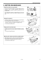
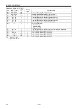
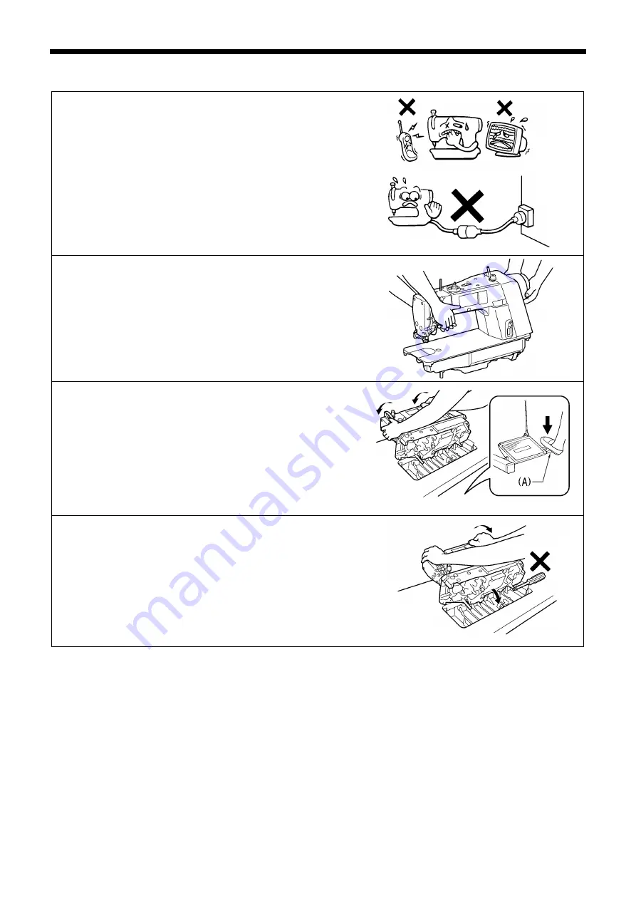
About the machine set-up location 


Do not set up this sewing machine near other equipment such as 

televisions, radios or cordless telephones, otherwise such 

equipment may be affected by electronic interference from the 

sewing machine. 


The sewing machine should be plugged directly into an AC wall 

outlet. Operation problems may result if extension cords are 

used. 


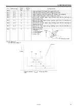
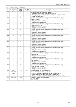
Carrying the machine 


The sewing machine should be carried by the arm and the pulley 

cover by two people as shown in the illustration. 

* Do not hold by any part other than the pulley cover. If this is not 

observed, it may result in damage to the sewing machine. 

* Do not hold the operation panel. 


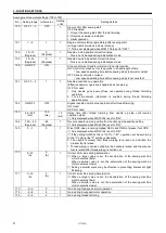
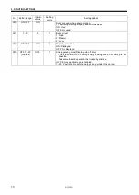
Tilting back the machine head 


Hold section (A) with your foot so that the table does not move, 

and then push the arm with both hands to tilt back the machine 

head. 

* Do not push the operation panel. 


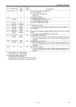
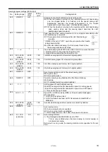
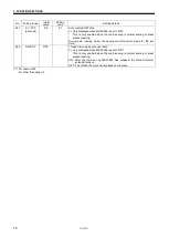
Returning the machine head to the upright position


1.  Clear away any tools, etc. which may be near the table holes. 

2.  While holding the face plate with your left hand, gently return the 

machine head to the upright position with your right hand. 

* Do not hold the operation panel. 


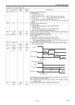
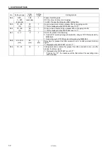
0475D 

0877D 

0878D 

0879D 

Summary of Contents for S-7300A

Page 1: ...S 7300A Please read this manual before making any adjustments SINGLE NEEDLE DIRECT DRIVE LOCK STITCHER WITH ELECTRONIC FEEDING SYSTEM AND THREAD TRIMMER SERVICE MANUAL ...

Page 2: ...FETY INSTRUCTIONS below and the whole of this manual to understand this product before you start maintenance As a result of research and improvements regarding this product some details of this manual may not be the same as those for the product you purchased If you have any questions regarding this product please contact a Brother dealer ...

Page 3: ...hich follow this term indicate situations where failure to follow the instructions could result in death or serious injury CAUTION The instructions which follow this term indicate situations where failure to follow the instructions may result in minor or moderate injury Symbols This symbol indicates something that you should be careful of The picture inside the triangle indicates the nature of the...

Page 4: ... cord from the wall outlet Lightning may cause problems with correct operation Do not connect anything to the USB port other than the USB memory If this is not observed problems with operation may result Installation Machine installation should only be carried out by a qualified technician Contact your Brother dealer or a qualified electrician for any electrical work that may need to be done The s...

Page 5: ...e hand is used the weight of the machine head may cause your hand to slip and your hand may get caught If an error occurs in machine operation or if abnormal noises or smells are noticed immediately turn off the power switch Then contact your nearest Brother dealer or a qualified technician If the machine develops a problem contact your nearest Brother dealer or a qualified technician Do not hold ...

Page 6: ...fety Secure the table so that it will not move when tilting back the machine head If the table moves it may crush your feet or cause other injuries Use both hands to hold the machine head when tilting it back or returning it to its original position If only one hand is used the weight of the machine head may cause your hand to slip and your hand may get caught When replacing parts and installing o...

Page 7: ...to get your hands caught when returning the machine head to its original position after it has been tilted 3 5 Be careful to avoid injury from the moving thread take up and pulley 6 Do not hold Problems with operation or injury may occur 7 Be sure to connect the ground If the ground connection is not secure you run a high risk of receiving a serious electric shock and problems with correct operati...

Page 8: ...S 7300A vi Control box Oil tank Transformer box 100 V 400 V system only 0874D ...

Page 9: ...S 7300A vii ...

Page 10: ... Hand switch and X over seam sensor 60 5 10 1 Cord holder and Thread wiper device assembly 60 5 10 2 Fase plate X over seam sensor and Hand switch assembly 61 5 11 Tension mechanism Other than premier specifications 62 5 12 Tension mechanism Premier specifications 63 5 13 Needle plate feed dog etc 64 5 14 Bobbin case rotary hook and thread trimmer mechanism 65 5 15 Feed mechanism 66 5 15 1 Disasse...

Page 11: ...ing 129 7 8 Adjusting the thread take up amount 3 specifications 130 7 9 Adjusting the presser foot floating amount minute lifting amount option 131 7 10 Adjusting the thread tension and tension release wire 132 7 10 1 Adjusting the lower backup pin for tension stud bracket assembly 132 7 10 2 Adjusting the tension stud bracket assembly position 133 7 10 3 Adjusting the tension release wire positi...

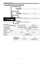
Page 12: ...h 4 4000 sti min Pitch 4 or less 4500 sti min More than pitch 4 4000 sti min Backtack sewing speed Standard feed locus Automatic 150 1 3000 sti min Manual 150 1 4000 sti min 1 Inching setting speed Max stitch length 5mm 7mm 5 mm at time of shipment Presser foot height Lifting lever 6mm Knee lifter 16mm Feed dog height 0 8mm 1 2mm Needle DB 1 DP 5 11 18 19 22 Motor AC servo motor Control circuit Mi...

Page 13: ...y cover by two people as shown in the illustration Do not hold by any part other than the pulley cover If this is not observed it may result in damage to the sewing machine Do not hold the operation panel Tilting back the machine head Hold section A with your foot so that the table does not move and then push the arm with both hands to tilt back the machine head Do not push the operation panel Ret...

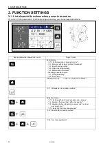
Page 14: ...dvanced 3 5 Input checking method 3 6 Output checking method 3 9 Maintenance information Clearing grease up counter 3 7 Protection setting 3 8 Error history Initialization mode Refer to the Instruction Manual 3 11 Software version updating method Adjustment menu 7 12 Setting method for standard depression strokes 7 4 Adjusting the upper shaft reference position 7 5 Adjusting the feed position maxi...

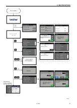
Page 15: ...S 7300A 3 FUNCTION SETTINGS 4 If the power is turned on without any key operations S 7300A 303P Turn on power 1202D ...

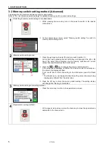
Page 16: ...same time to display only the memory switches with current values that are different from their initial values 2 Press the or key to change the memory switch value 2 If the value that is displayed is different from the value that is currently set the value in the display will flash If you would like to return the setting to the initial value press the Reset key The Reset key is only displayed when...

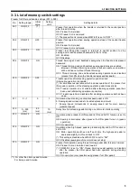
Page 17: ...of the presser foot lifter pedal operation of the standing operation pedal takes priority ON Treadle operation is still enabled after standing operation pedal has been used alternating operation is possible OFF Treadle operation is disabled after standing operation pedal has been used 011 0 1 0 1 Operation when standing up variable speed pedal is ON 0 Sewing speed corresponds to treadle depression...

Page 18: ...ised and lowered by depressing the treadle backward OFF Above operation is not possible 055 ON OFF 2 Presser foot operation when machine motor stops with the presser foot in the raised position and then the presser foot is lowered and the treadle is then moved to the neutral position Displayed when MSW 851 is set to ON ON Presser foot is raised The presser foot does not lift when MSW 851 is set to...

Page 19: ...ble speed range starting point S3 for standing up variable speed pedal 085 7 7 0 1 Sewing motor high speed range reaching point S4 for standing up variable speed pedal 086 2 2 0 1 Sewing motor variable speed range starting point S3 for standing up variable speed pedal 087 2 2 0 1 Sewing motor high speed range reaching point S4 for standing up variable speed pedal 088 0 3 0 1 Treadle speed curve 0 ...

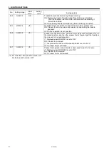
Page 20: ...on stop operation after thread trimming ON Used OFF Not used 153 50 500 ms 150 ms 10 ms Delay time after thread trimming from needle up stop until reverse operation starts Only displayed when MSW 152 is set to ON 154 120 40 Degrees 60 Degrees 1 Reverse needle up stop position from needle up stop position setting Only displayed when MSW 152 is set to ON 155 0 1 0 1 Wiper OPE when reversing highest ...

Page 21: ...e This speed is used when MSW 150 is set to ON 184 150 3000 sti min 3000 sti min 100 Start backtacking limit speed This is the upper limit for the start backtack sewing speed setting and the actual sewing speed will not be lower than the setting value for MSW 181 186 150 3000 sti min 3000 sti min 100 End backtacking limit speed This is the upper limit for the end backtack sewing speed setting and ...

Page 22: ... Feed timing correction amount for Special locus 2 253 50 50 0 1 Feed timing correction amount for Special locus 3 254 50 50 6 1 Feed timing correction amount for slow start 255 0 2 2 1 Slow start feed locus 0 Normal locus 1 Special locus 1 2 Special locus 2 256 50 50 0 1 Feed timing correction amount for auto X over seam sewing mode 257 100 1 15 1 Auto X over seam sewing parameter A 258 500 3 3 1...

Page 23: ...l function 305 0 1 1 1 Program common function program individual function settings AUTO auto thread trimming 0 Program common function 1 Program individual function 306 0 1 0 1 Program common function program individual function settings Slow start 0 Program common function 1 Program individual function 307 0 1 1 1 Program common function program individual function settings Special locus 0 Progr...

Page 24: ... 351 1 3 2 1 Buzzer level 1 High 2 Medium 3 Low 352 ON OFF ON 1 Display for model ON Displayed OFF Not displayed 353 OFF 1 20 minutes OFF 1 Energy saving mode Display auto off time The screen will turn off during energy saving mode but sewing is still possible Take care to avoid operating the treadle by mistake OFF Energy saving mode is disabled 1 20 Panel idle time before energy saving mode turns...

Page 25: ...ginal pattern 404 300 4000 sti min 4000 100 2nd stitch sewing speed for slow start original pattern 405 300 4000 sti min 4000 100 3rd stitch sewing speed for slow start original pattern 406 300 4000 sti min 4000 100 4th stitch sewing speed for slow start original pattern 407 ON OFF OFF Synchronize with main pitch of backtack sewing pitch ON Synchronized OFF Not synchronized 450 ON OFF OFF Correcti...

Page 26: ...ng or pleat presser sewing During auto running mode the sewing machine motor stops for the set time 462 ON OFF OFF Thread trimming by auto operation Only displayed when MSW 459 is set to ON This is only enabled when the main sewing is normal sewing or pleat presser sewing ON After the time set by MSW 460 has elapsed the thread trimmer solenoid turns on OFF The thread trimmer solenoid does not oper...

Page 27: ...olenoid signal has been turned OFF when presser foot is raised 559 OFF 1 2 OFF 1 Feed control ON OFF when thread wiper OFF Disabled 1 Not used Operation is the same as if set to OFF 2 Enabled this is useful for reducing thread wiping errors For 3 specifications this only operates when the stitch pitch is 3 mm or less during thread trimming 560 1 200 ms 1 ms 1 ms Thread wiping and presser foot lift...

Page 28: ...control This is displayed when MSW 550 is set to 1 567 0 1 0 1 Control for presser foot lowering 0 Control P F lowering timing with detected voltage of P F lifter solenoid by MSW 569 1 Control timing for P F lifter solenoid lowering by MSW 568 568 20 120 ms 40 ms 5 ms Delay time for presser foot lifter solenoid to turn on after presser foot drop signal Displayed when MSW 567 is set to 1 569 10 15 ...

Page 29: ...tion mode Specifications and destination settings 800 to 899 No Setting range Initial value Setting units Setting details 850 0 2 8 1 Language 0 Chinese 1 English 2 Japanese This is not initialized during initialization mode 851 ON OFF 9 PRE foot operation by treadle ON Europe specifications Set by MSW 001 MSW 055 OFF Other than Europe and America After T T when treadle is retuned to neutral PRE f...

Page 30: ...OFF 1 2 OFF 1 Function of option input 2 This is not displayed when MSW 950 is set to 3 Option input 2 functions as a speed selection medium speed switch OFF Disabled 1 Operation prohibition input operation by operating the treadle at Low etc is prohibited 2 Variable input for option output 3 Only enabled when MSW 960 is set to 4 952 OFF 1 OFF 1 Function of option input 3 This is not displayed whe...

Page 31: ... No stitch number control 1 to 99 Stitch number control enabled 962 5 30 seconds 10 seconds 1 Puller output ON timing when sewing motor stops Displayed when MSW 960 is set to 1 963 0 990 ms 10 ms 10 Delayed timing from presser foot solenoid is ON to pneumatic wiper output ON Displayed when MSW 960 is set to 3 964 0 1 2 0 seconds 2 0 seconds 0 1 Pneumatic wiper output ON time Displayed when MSW 960...

Page 32: ...previous screen was a screen at which sewing is possible NOTE When the power indicator is illuminated the sewing machine may still start up even though the screen is switched off If you would like to temporarily cancel energy saving mode press the menu key or the home key Energy saving mode will then be canceled and the display will return to the previous screen However if an error or a lower thre...

Page 33: ...he memory switch number 1 to 353 2 Press the or key to set the time 2 until energy saving mode is activated Here it is set to activate after 5 minutes The initial setting is OFF energy saving mode disabled 3 Press the OK key to store the memory switch setting The setting display will change from flashing to illuminated 3 Memory switch setting mode exiting method Press the return key to return to t...

Page 34: ...enu screen 2 At the special menu screen select Input check 3 The item number 1 item name 2 and input status 3 will be displayed 4 Press the or key 4 to select the item to be checked Press the return key 5 to return to the special menu screen 2 To exit from the special menu At the special menu screen press the home key to close the special menu and switch to the home screen 1 2 3 4 4 5 ...

Page 35: ...and lower the presser foot IN 09 Hand switch A OFF 7 OFF 1 7 Changes within the range given at left Press hand switch A IN 10 Hand switch B OFF 2 OFF 1 2 Changes within the range given at left Press hand switch B IN 11 Knee switch or presser foot switch of standing up pedal ON OFF ON when pressed Press the knee switch or the presser foot switch of the standing operation pedal IN 12 Speed input fro...

Page 36: ... The item number 1 and item name 2 will be displayed 4 Press the or key 4 to select the item to be checked If you select items OUT 4 to OUT 6 the output status 3 will also be displayed You can display the actual sewing machine speed for checking Press the return key 5 to return to the special menu screen 2 To exit from the special menu At the special menu screen press the home key to close the spe...

Page 37: ...aft middle speed Stopped During operation the actual machine speed is also displayed in the bottom right of the screen Operate at 2000 sti min while the treadle is ON Set pedal to OFF to stop OUT 06 Upper shaft high speed Stopped During operation the actual machine speed is also displayed in the bottom right of the screen Operate at 4000 sti min while the treadle is ON Set pedal to OFF to stop OUT...

Page 38: ...r key to select the desired setting A or B Protect settings can be carried out at any time B Protect settings cannot be carried out unless USB media is inserted 3 Press the OK key to confirm the setting 3 Protect for individual setting Protect settings can be carried out individually for each function For details refer to Protection setting list 1 At the protect setting screen select Protect for i...

Page 39: ...functions from 1 to 15 1 At the protect setting screen select All Allowed OFF 2 Press the OK key to confirm the setting 5 All prohibited You can turn protection on for all functions from 1 to 15 1 At the protect setting screen select All prohibited ON 2 Press the OK key to confirm the setting ...

Page 40: ...y Main portion setting Add Delete step Front BT setting End BT setting Program individual function setting Program common function setting Memory switch setting for operator Memory switch setting for maintenance Production counter setting USB media read write Short cut key setting Design stitch setting Initialization Adjustment mode Hand switch X over seam sensor correction ...

Page 41: ...om the left each error item contains a history number an error code the accumulated motor running time in seconds 10 digits and the power supply voltage in the control box NOTE E064 E067 E095 E400 E424 E440 E441 E705 and E880 E889 do not remain in the error history and so they are not displayed 5 Press the or key 2 to change the screen one page at a time Up to 96 error items 01 96 are stored in or...

Page 42: ...to switch to the confirmation screen for clearing the error history 2 Press the OK key 5 to clear the whole of the error history Once clearing is finished the buzzer will sound for 1 second and all error items will be displayed as E Press the return key 3 to return to the error history screen If you press the return key 3 without pressing the OK key 5 the error history will not be cleared 4 To exi...

Page 43: ...screen 3 Select Maintenance information 4 The maintenance screen number 1 maintenance information 2 and the corresponding value 3 will be displayed Each screen displays two items of maintenance information 5 Press the or key 4 to select the screen 1 to 4 that you would like to check Press the return key 5 to return to the special menu screen 2 To exit from the special menu At the special menu scre...

Page 44: ...ed REF position correction value Displays the feed reference position correction value 300 300 3 Grease up counter For 3 specifications 0 102 is displayed If the value is 100 or more the grease up warning screen is displayed when the power is turned on For 0 specifications 0 is displayed Grease up time For 3 specifications 4000 is displayed For 0 specifications 0 is displayed 4 Accumulated power o...

Page 45: ...rsion screen and the IPL program version screen each time you press the half stitch key At the control program version screen the main control program version and the panel control program version are displayed At the IPL program version screen the main IPL program version the panel IPL program 1 version and the panel IPL program 2 version are displayed 3 Exiting software version checking mode Pre...

Page 46: ...software version update mode 1 While pressing the half stitch key turn on the power to switch to the version update selection screen 3 Version update selection mode 1 Check that the version number 1 for the main control program that you are going to update is correct 2 Press the upper Update key 2 to start the version update 4 While version updates are running 1 While version updating is in progre...

Page 47: ...date mode 1 While pressing the half stitch key turn on the power to switch to the version update selection screen 3 Version update selection mode 1 Check that the version number 1 for the panel control program that you are going to update is correct 2 Press the lower Update key 2 to start the version update 4 While version updates are running 1 While version updating is in progress the progress st...

Page 48: ...ewing machine on the screen 1 Starting serial number checking mode 1 While pressing the menu key and the half stitch key turn on the power to switch to the serial number checking screen 2 Serial number checking mode 1 The serial number 1 of the sewing machine will be displayed 2 To exit turn off the power 1 ...

Page 49: ...ft and needle bar mechanism The mechanisms operate in the order of the numbers given in the illustrations 1 Sewing machine motor 2 Timing pulley D 3 Timing belt 4 Timing pulley U 5 Upper shaft 6 Thread take up crank 7 Needle bar crank 8 Needle bar crank rod assembly 9 Needle bar clamp 10 Needle bar 1 Needle bar bush U 2 Needle bar bush D 1087D The needle bar is guided by needle bar bush U 1 and ne...

Page 50: ...NICAL DESCRIPTIONS 39 4 2 Lower shaft and rotary hook mechanism 1 Main shaft motor 2 Timing pulley U 3 Pulley 4 Lower shaft 5 Lower shaft gear 6 Rotary hook shaft gear 7 Rotary hook shaft 8 Rotary hook assembly 1267D ...

Page 51: ...l movement 1 Main shaft motor 2 Upper shaft 3 Pulley 4 Lower shaft 5 Vertical feed assembly 6 Lifting feed shaft unit 7 Feed bar assembly 8 Feed dog 1138D 1 P motor assembly 2 Feed rocker link unit 3 Feed rock shaft 4 Feed rock bracket arm 5 Feed bar shaft assembly 6 Feed bar assembly 7 Feed dog 1275D ...

Page 52: ...perate the sewing machine 1 Oil feeding pocket 2 Oil tank 3 To upper shaft thread take up and needle bar etc 0 specifications 3 To rotary hook and rotary hook shaft 0 3 specifications 4 Remaining return oil 1124D 1 Oil gauge window 2 Upper reference line 3 Oil gauge 4 Lower reference line 5 Plunger pump Fine adjustments can be made to the lubrication amount for the rotary hook using the adjustment...

Page 53: ...imming mechanism operation sequence The illustration below shows the mechanism with the high speed rotary hook removed 1 When thread rimming signal is input 1 Solenoid plunger 2 Solenoid lever 3 Thread trimmer cam lever shaft 4 Roller Moves to above 1 1 Thread trimmer cam 1039D ...

Page 54: ...ller 3 Slide block 4 Forked shaft 5 Thread trimmer lever 6 Upper knife connecting rod 7 Upper knife holder 8 Upper knife 1209D 1041D 1210D 1 Thread trimmer cam 2 Roller 3 Slide block 4 Forked shaft 5 Thread trimmer lever 6 Movable knife connecting rod 7 Movable knife holder 8 Movable knife 6 Lower knife connecting rod 7 Lower knife holder 8 Lower knife ...

Page 55: ...A 4 MECHANICAL DESCRIPTIONS 44 3 Thread trimming complete and operation stopped Thread trimmer cam lever axial direction 1 Extension spring 2 Thread trimmer cam lever 3 Solenoid lever 4 Solenoid plunger 1042D ...

Page 56: ...nnecting rod 5 Upper knife holder 6 Upper knife 4 Lower knife connecting rod 5 Lower knife holder 6 Lower knife 1 Forked shaft return spring 2 Forked shaft 3 Thread trimmer cam lever 4 Roller 1211D 1212D 1044D 3 Thread trimmer lever 4 Movable knife connecting rod 5 Movable knife holder 6 Movable knife 1 Forked shaft return spring 2 Forked shaft 3 Thread trimmer cam lever 4 Roller ...

Page 57: ...r cam 2 Return roller 3 Slide block 4 Forked shaft 5 Thread trimmer lever 6 Upper knife connecting rod 7 Upper knife holder 8 Upper knife 6 Lower knife connecting rod 7 Lower knife holder 8 Lower knife 1 Thread trimmer cam 2 Return roller 3 Slide block 4 Forked shaft 5 Thread trimmer lever 6 Movable knife connecting rod 7 Movable knife holder 8 Movable knife ...

Page 58: ...ease plate 10 to return When the thread trimming signal turns off parts such as the tension release wire 2 return to their original positions Presser foot is raised using the knee lifter plate assembly 1 Knee lifter plate assembly 2 Knee lifter lever D 3 Knee lifter connecting rod 4 Knee lifter F 5 Knee lifter R 6 Knee lifter bar 7 Knee lifter lever D 8 Knee lifter connecting rod 9 Presser bar lif...

Page 59: ... signal turns off parts such as the tension release wire 2 return to their original positions Presser foot is raised using the knee lifter plate assembly 1 Knee lifter plate assembly 2 Knee lifter lever D 3 Knee lifter connecting rod 4 Knee lifter F 5 Knee lifter R 6 Knee lifter bar 7 Knee lifter lever D 8 Knee lifter connecting rod 9 Presser bar lifter lever 10 Lifting plate 11 Presser bar 12 Pre...

Page 60: ...wiper link L 5 Thread wiper lever B assembly 6 Thread wiper crank assembly 7 Lever stopper assembly 8 Thread wiper Thread wiper signal is turned off 1 Thread wiper spring 2 Thread wiper spring 3 Thread wiper solenoid Returns Thread wiper signal is input 1 Thread wiper solenoid 2 Thread wiper rod 3 Thread wiper crank assembly 4 Thread wiper Thread wiper signal is turned off 1 Thread wiper spring 2 ...

Page 61: ...iginal position If only one hand is used the weight of the machine head may cause your hand to slip and your hand may get caught Be sure to wear protective goggles and gloves when handling the lubricating oil and grease so that they do not get into your eyes or onto your skin otherwise inflammation can result Furthermore do not drink the oil or eat the grease under any circumstances as they can ca...

Page 62: ... Cut 1 Sewing machine motor connector 4 pin 2 Feed motor connector 6 pin 3 Power supply connector 3 pin 4 Sewing machine motor encoder connector 16 pin 5 Feed motor encoder connector 6 pin 6 Hand switch connector 12 pin 7 Operation panel connector 10 pin 8 Solenoid connector 10 pin 1109D ...

Page 63: ...5 DISASSEMBLY 52 5 4 Covers 5 4 1 Top cover and pulley cover 0993D 0994D 1 Screws 4 pcs 2 Pulley cover 3 Screws 5 pcs 4 Screw 5 Knee lifter adjustment screw Nut 6 Bobbin winder tension assembly Nut 7 Top cover ...

Page 64: ...ISASSEMBLY 53 5 4 2 Panel 0996D 1022D 1215D 1 Operation panel connector 10 pin 2 Screws 2 pcs 3 Cord holders 2 pcs 4 Screw 5 Harness clamp 6 Cap 7 Screw 8 Set screws 2 pcs 9 Panel assembly 10 Panel supports 2 pcs ...

Page 65: ...olenoid 1 Nut 2 Screw 3 Wire holder D 4 Screw 5 Cord holder 6 Screw 7 Wire holder U 8 Tension release wire Remove from the tension release plate 1 and pull out 1 Tension release plate 1059D 9 Screw 10 Cord holder 11 Screw 12 Cord holder 13 Screw 14 Cord holder 1061D 1060D ...

Page 66: ...S 7300A 5 DISASSEMBLY 55 15 Screws 4 pcs 16 Socket bolt 17 Washer 18 Collar 19 Rubber cushion Remove from 18 20 thread trimmer solenoid assembly 1062D ...

Page 67: ...SASSEMBLY 56 5 6 Wick holder and oil tube 0 specifications only 1126D 1 Wick Unite the knot 2 Screw 3 Wick holder 4 Screw 5 Tube holder U 6 Vinyl tube Remove from wire cord holder 1 and pull out 1 Wire code holder ...

Page 68: ...ank 6 Vinyl tube Pull out 7 Vinyl tube Pull out 1 Lubricating oil 2 Rubber cap 0 specifications only Pull Remove Slide Pull out 1 Hold a dish under the lubricating oil drain hole and then remove the screw 1 to drain out the lubricating oil 1 2 Install the screw 1 to the lubricating oil drain hole 1128D Knot 0 specifications only ...

Page 69: ...s 2 pcs 2 Screws 6 pcs 3 Bed bottom cover 1 Lubricating oil 1130D 1 Hold a dish under the lubricating oil drain hole and then remove the screw 1 to drain out the lubricating oil 1 2 Install the screw 1 to the lubricating oil drain hole 1094D 1 Stand L 2 Stand R 3 pcs ...

Page 70: ...S 7300A 5 DISASSEMBLY 59 5 9 Needle and presser foot 1197D Integrated finger guard type 1 Set screw 2 Needle 3 Screw 4 Washer 5 Finger guard 6 Presser foot ...

Page 71: ...r device assembly 0998D For specifications with thread wiper For specifications without thread wiper 0999D 1 Screws 8 pcs 2 Cord holder U 3 Cord holder D 4 Cord holders 2 pcs 5 Cord holder 6 Thread wiper assembly 1 Screws 6 pcs 2 Cord holder U 3 Cord holders D 2 pcs 4 Cord holders 2 pcs 5 Cord holder ...

Page 72: ...1 5 10 2 Fase plate X over seam sensor and Hand switch assembly 1 Screws 4 pcs 2 Face plate assembly 3 Screws 3 pcs 4 X over seam sensor assembly 5 Screws 2 pcs 6 Hand switch assembly 1001D 1000D 1002D Premier specifications ...

Page 73: ...than premier specifications 1 Set screw 2 Pre tension assembly S 3 Set screw 4 Thread tension bracket assembly 5 Tension release pin 6 Tension release bar 7 Screw 8 Arm thread guide R 9 Set screw 10 Thread guide arm 11 Needle bar bush D thread guide 1216D ...

Page 74: ...ly P 3 Tension release pin A 4 Tension release bar A 5 Set screw 6 Thread tension bracket assembly 7 Thread take up spring stopper 8 Stopper spring 0991D 9 Tension release pin 10 Tension release bar assembly 11 Screw 12 Arm thread guide R 13 Set screw 14 Thread guide arm 15 Needle bar bush D thread guide ...

Page 75: ...S 7300A 5 DISASSEMBLY 64 5 13 Needle plate feed dog etc 1 Flat screws 2 pcs 2 Needle plate 3 Slide plate 4 Screws 2 pcs 5 Feed dog 6 Screw 7 Ruler plate 1198D ...

Page 76: ...le 9 Screw Loosen 9 Screw Loosen 1217D 10 Thread trimmer lever assembly 10 Thread trimmer lever assembly 11 Screw 12 Washer 13 Lower thread finger 14 Set screw Loosen 15 Thread trimmer cam lever shaft Pull out 16 Rubber cushion 17 Collar 18 Extension spring 19 Thread trimmer lever assembly 20 Rubber cushion Remove from hole Other than premier specifications Other than premier specifications 21 For...

Page 77: ...d mechanism 5 15 1 Disassembling the feed mechanism 1139D 1 Set screws 2 pcs Loosen 2 Screw Loosen 3 Feed rock shaft Pull out 4 Washer 5 Set screws 2 pcs Loosen 6 Feed bar unit 7 Set screws 2 pcs Loosen 8 Feed rocker link unit 9 Washer ...

Page 78: ...connector 6 pin 12 Tube Remove from tube band 1 13 Screw 14 Socket bolts 4 pcs 15 Feed motor 1 Tube band 2 Motor cover 3 Motor bracket 1 Screw Loosen 2 Lifting feed shaft unit 3 Washer 4 Vertical feed assembly 5 Screw Loosen 6 Feed bar shaft unit 7 Washer 8 Feed rock bracket arm 9 Feed bar assembly 1140D 1263D 1264D ...

Page 79: ...r spring 4 Washer 5 Screw 6 Presser bar guide bracket 7 Presser bar Pull upward 8 Retaining ring E 9 Presser bar lifter lever spring 10 Retaining ring E 11 Washer 12 Set screw 13 Presser bar lifter lever shaft Pull out 14 Tension release plate 15 Washer 16 Presser bar lifter lever assembly 1097D 1096D 1095D ...

Page 80: ... pulley 1101D 1 Shoulder screw 2 Presser bar lifter lever assembly Remove in the direction of the allow 3 Shoulder screw 4 Knee lifter lever assembly Remove in the direction of the allow 5 Shoulder screw 6 Knee lifter bar 1104D 1 Set screws 2 pcs 2 Tension pulleyassembly ...

Page 81: ... 1105D 1 Rubber cap 2 Rubber cap 3 Rubber cap 4 Screw Loosen 5 Needle bar 6 Needle bar clamp 7 Needle bar guide slide block 1146D 8 Needle bar bush U 9 Set screws 3 pcs Loosen 10 Needle bar crank 11 Set screws 2 pcs Loosen 12 Thread take up lever assembly 13 Washer 1147D ...

Page 82: ...S 7300A 5 DISASSEMBLY 71 5 20 Pulley and timing pulley U 1 Screw Loosen Pass the tool through hole A 2 Bearing holder Slide 3 Set screws 2 pcs 4 Pulley assembly 1268D ...

Page 83: ...2 5 21 Main shaft motor 1 Screw 2 Harness Clamp 3 Sewing machine motor encoder connector 16 pin 4 Sewing machine motor connector 4 pin 5 Set screws 2 pcs 6 Set screws 4 pcs 7 Sewing machine motor 1 Timing pulley D 1143D 1144D ...

Page 84: ... 22 Timing belt 5 23 Timing pulley U 1107D 1 Timing pulley U Remove the belt from the upper shaft and pass it over the upper shaft 2 Timing pulley D Remove the belt from the lower shaft 1269D 1 Set screws 2 pcs 2 Timing pulley U ...

Page 85: ...74 5 24 Lower shaft lower shaft gear and lower shaft fan 1 Set screws 2pcs 2 Set screws 2pcs Loosen 3 Set screws 2pcs Loosen 4 Timing pulley D 5 Lower shaft assembly 6 Spacers 2pcs 7 Lower shaft gear 8 Lower shaft fan 1270D ...

Page 86: ...t rotary hook shaft gear and thread trimmer cam 1134D 1 Rubber cap 2 Cap screw pump 3 Spring 4 Plunger 5 Set screws 2 pcs Loosen 6 Set screws 2 pcs Loosen 7 Set screws 2pcs 8 Spacers 2pcs 9 Rotary hook shaft 10 Rotary hook shaft gear 11 Thread trimmer cam ...

Page 87: ...n 2 Thread wiper device assembly 1 Set screws 2 pcs Loosen 2 Set screw collar Remove 3 Screws 2 pcs Loosen 4 Thread wiper device assembly Remove 5 Thread wiper lever shaft Loosen 6 Washer 7 Screws 2 pcs Loosen 8 Lever stopper assembly 9 Set screw Loosen 10 Thread wiper crank unit Pull out 1145D 1119D ...

Page 88: ...ly one hand is used the weight of the machine head may cause your hand to slip and your hand may get caught Be sure to wear protective goggles and gloves when handling the lubricating oil and grease so that they do not get into your eyes or onto your skin otherwise inflammation can result Furthermore do not drink the oil or eat the grease under any circumstances as they can cause vomiting and diar...

Page 89: ...ad trimmer cam 3 Rotary hook shaft gear 4 Set screw Align with screw stop 5 Set screw Tighten 6 Set screw Align with screw stop 7 Set screw Tighten 8 Rotary hook shaft Check that it rotates smoothly with no play 9 Spacers 2pcs 10 Set screws 2pcs Provisionally tighten 11 Plunger 12 Spring 13 Cap screw pump 14 Rubber cap 1135D 12 1mm ...

Page 90: ...8 Timing pulley D 9 Spacer 4 8 10 Set screw Align with screw stop 11 Spacer 4 8 12 Set screw Tighten Turn the rotary hook shaft gear a so that the upper set screw b is facing toward the front and also turn the lower shaft gear c so that the lower set screw d is facing toward the front and then align the blade of the rotary hook gear a with the blade of the lower shaft gear c In this position align...

Page 91: ...m 1 Upper shaft assembly Insert 2 Timing pulley U Pass the upper shaft through 3 Set screws 2pcs Align the first set screw in the rotation direction with the screw stop 1120D Align the edge of timing pulley U with the reference line Screw stop side ...

Page 92: ...ley Lower shaft side Upper shaft side 0 1mm 1148D 1 Timing belt 1 Set screw Set so that the first set screw 1 in the rotation direction of timing pulley D is facing downward 1149D Set the needle tip and needle plate to the positions shown in the illustration Belt setting position 1276D ...

Page 93: ...ASSEMBLY 82 6 5 Pulley and main shaft motor 1122D 1 Pulley assembly 2 Set screws 2pcs Align the first set screw in the rotation direction with the screw stop 3 Bearing holder 4 Screw Pass the tool through hole A ...

Page 94: ...re the the sewing machine motor 2 with the four socket bolts 4 NOTE Turn the machine pulley 5 and check that it does not move together with the machine motor shaft 3 Tighten the two set screws 6 to secure the machine motor shaft First tighten the set screw 6 on the screw stop side The reference line 7 is the mark on the screw stop 1203D Label Screw stop side 1204D Screw stop side ...

Page 95: ...S 7300A 6 ASSEMBLY 84 4 Connect the 16 pin sewing machine motor encoder connector 8 and the 4 pin sewing machine motor connector 9 and then install the harness clamp 10 1205D ...

Page 96: ...en the set screw at A First tighten the set screw at A At this time align the set screw at A with groove B in the tension pulley 1154D 1 Knee lifter bar 2 Shoulder screw 3 Knee lifter lever assembly 4 Shoulder screw 5 Presser bar lifter lever assembly 6 Shoulder screw Pass the knee lifter bar 1 through the hole near the front of the bed ...

Page 97: ...le bar 10 Screw Tighten 11 Set screws 2 pcs Align with screw stop 12 Rubber cap 13 Rubber cap 14 Rubber cap 1157D Refer to 7 8 Adjusting the thread take up amount when carrying out assembly Refer to 7 6 Adjusting the needle bar height when carrying out assembly 1155D 1156D Turn the machine pulley back and forth 2 or 3 times by approximately 90 each time to move the thread take up lever assembly 2 ...

Page 98: ... 5 Washer 6 Retaining ring E 7 Presser bar lifter lever spring 8 Retaining ring E 9 Set screw 1160D 1159D 1158D 10 Presser bar Insert 11 Presser bar guide bracket 12 Screw Provisionally tighten 13 Washer 14 Presser bar spring 15 Spring guide 16 Presser adjusting screw Tighten at the screw stop so that there is no play in the presser bar lifter lever shaft 1 ...

Page 99: ...EMBLY 88 6 10 Feed bar unit mechanism 1 Feed bar assembly 2 Feed rock bracket arm 3 Washer 4 Feed bar shaft assembly 5 Screw Tighten 6 Vertical feed assembly 7 Washer 8 Lifting feed shaft unit 9 Screw Tighten 1194D ...

Page 100: ...ft 1 2 Washer 3 Feed rock shaft 4 Feed rocker link unit 5 Set screws 2 pcs 6 Washer 1 Lower shaft 2 Feed shaft bush R 1161D Be careful to tighten against screw stop Place against edge Pass through the feed bar unit 1 and the feed rocker link unit 4 Place onto feed rocker shaft 3 ...

Page 101: ...or bracket 10 Socket bolts 4 pcs 11 Set screws 2 pcs 1 Motor shaft Align the screw stop on the motor shaft 1 with the screw stop side of the PM arm 8 First tighten the set screw 11 on the screw stop side Check that the PM arm 8 moves smoothly Place the motor bracket 9 against the top right of the processed surface of the bed ...

Page 102: ...e lower shaft 1 and provisionally tighten 13 Set screws 2 pcs Provisionally tighten 14 Screw After adjusting the feed dog position fully tighten 15 Set screws 2 pcs Align with the reference line on the lower shaft 1 and fully tighten 1 Lower shaft 1167D Reference line ...

Page 103: ...n a straight line 3 Loosen the screw c of the feed rocker bracket arm 4 Adjust the feed rocker bracket arm so that the clearance between the front of the feed dog and the needle plate is 0 5 mm for specifications 3 mm for 5 specifications and 0 1 mm at the left side 5 Tighten the screw c of the feed rocker bracket arm 1170D Move the feed dog forward 3 specifications 0 5mm 5 specifications 3mm 0 1m...

Page 104: ...r cam lever shaft 10 Set screw 11 Lower thread finger 12 Washer 13 Screw 14 Thread trimmer lever assembly 14 Thread trimmer lever assembly 15 Screw 15 Screw Provisionally tighten 16 Thread trimmer lever spring Insert into the hole 17 Knife holder presser plate 18 Flat screws 3 pcs 18 Fixed knife 19 Flat screws Tighten Insert the slide block into the forked shaft Assemble while referring to Adjusti...

Page 105: ... so that it becomes impossible to measure the actual oil level accurately 2 The amount of oil which overflows from a will very depending on the angle at the machine head is tilted back at Tilt back the machine head while the head rest 2 is installed in the correct position 3 If you add too much oil oil will leak from the air holes during operation so after adding oil wait until oil stops overflowi...

Page 106: ...EMBLY 95 6 13 2 Oil tank 1 Vinyl tube Insert 2 Oil tank 3 Screws 2 pcs 4 Oil tank guard 5 Screw 6 Vinyl tube Insert 7 Screw 1 Rubber cap 0 specifications only Insert Insert Slide Fit 1129D Knot 0 specifications only ...

Page 107: ...S 7300A 6 ASSEMBLY 96 1094D 6 14 Stand 1 Stand L 2 Stands R 3 pcs ...

Page 108: ...fted by the lifting lever b 1 Use the lifting lever b to lift the presser foot a 2 Move the presser bar c up or down to adjust the height of the presser foot a so that it is 6 mm above the top of the needle plate In addition adjust so that the groove in the presser foot a is parallel to the groove in the needle plate and so that the needle hole in the needle plate is at the center of the groove in...

Page 109: ...switch assembly 2 Screws 2 pcs Provisionally tighten Lower the work clamp and then tighten the screw 4 so that the distance between the presser bar bracket c and the top of the X over seam sensor 3 is 21 5 mm while the presser foot a and the needle plate b are touching 21 5mm 3 X over seam sensor assembly 4 Screws 3 pcs Premier specifications ...

Page 110: ... Face plate 6 Screws 4 pcs 1005D 7 Screws 2pcs Fully tighten 1006D Install so that the arm and the face plate are correctly aligned Place the cushion a of the hand switch 1 against the arm b and then fully tighten the screw 7 ...

Page 111: ...7D 1 Cord holder 2 Cord holder U 3 Cord holders D 2 pcs 4 Cord holders 2 pcs 5 Screws 6 pcs 1008D 1 Thread wiper assembly 2 Cord holder U 3 Cord holder D 4 Cord holders 2 pcs 5 Cord holder 6 Screws 8 pcs For specifications with thread wiper For specifications without thread wiper ...

Page 112: ...ter adjustment 7 Screw Loosen Fully tighten after adjustment 1112D 1111D 1110D Solenoid lever Touching Insert into the rubber cushion 3 Set so that there are no gaps at A B and C when the thread trimmer solenoid is at the ON position and then tighten 2 in the illustration below Set so that there are no gaps at D and E when the thread trimmer solenoid is at the OFF position and then tighten 6 and 7...

Page 113: ... 2 Harnesses 1114D 1 Cord holder 2 Screw 3 Cord holder 4 Screw 5 Cord holder 6 Screw Bind the panel and main shaft motor harnesses together also Bind the harnesses of the feed motor and the thread trimmer solenoid together 1113D ...

Page 114: ...in the bed at F inside hole Install the end to the tension release plate 1 Secure the wire at the position where the wire sheath a protrudes by approximately 18 mm 1116D 18mm 1121D Secure the wire at the position where the threaded section b protrudes by approximately 5 mm 5mm Assemble while referring to Adjusting the thread tension mechanism 1115D 1 Tension release wire ...

Page 115: ... guide R 5 Screw 6 Tension release bar 7 Tension release pin 8 Thread tension bracket assembly 9 Set screw 10 Pre tension assembly S 11 Set screw Assemble while referring to Adjusting the arm thread guide R 1219D Assemble while referring to Adjusting the thread take up spring Assemble while referring to Adjusting the thread tension and tension release wire ...

Page 116: ...ension release bar assembly 7 Tension release pin 8 Stopper spring 9 Thread take up spring stopper 10 Thread tension bracket assembly 11 Set screw 12 Tension release bar A 13 Tension release pin A 14 Pre tension assembly P 15 Set screw 0992D Assemble while referring to Adjusting the arm thread guide R Assemble while referring to Adjusting the thread take up spring Assemble while referring to Adjus...

Page 117: ...nly 6 21 Needle plate feed dog etc 1127D 1 Vinyl tube Insert Insert into wire cord holder 1 2 Tube holder U 3 Screw 4 Wick holder 5 Screw 6 Wick Clamp 1 Wire cord holder 1201D 1 Ruler plate 2 Screw 3 Feed dog 4 Screws 2 pcs 5 Slide plate 6 Needle plate 7 Flat screws 2 pcs ...

Page 118: ... support 2 pcs 2 Panel edge cushion 3 Panel assembly 4 Set screws 2 pcs 5 Screw 6 Cap 7 Cord holders 2 pcs 8 Screws 2 pcs 9 Harness clamp 10 Screw 11 Operation panel connector 10 pin 1009D 1023D 1010D Install the shielded wire together with the cord holder ...

Page 119: ... ASSEMBLY 108 6 22 2 Top cover and pulley cover 1011D 1012D 1 Top cover 2 Screw 1 pcs 3 Screws 4 pcs 4 Screw 5 Knee lifter adjustment screw Nut 6 Bobbin winder tension assembly Nut 7 Pulley cover 8 Screws 4 pcs ...

Page 120: ...0 pin 2 Operation panel connector 10 pin 3 Hand switch connector 12 pin 4 Feed motor encoder connector 6 pin 5 Sewing machine motor encoder connector 16 pin 6 Power supply connector 3 pin 7 Feed motor connector 6 pin 8 Sewing machine motor connector 4 pin 1136D ...

Page 121: ...nsert 2 Set screws 2 pcs Tighten 3 Lever stopper assembly 4 Screws 2 pcs Tighten 5 Washer 6 Thread wiper lever shaft 7 Thread wiper device assembly 8 Screws 2 pcs Tighten 9 Set screw collar 10 Set screws 2 pcs Tighten 1 Adjust the direction of the thread wiper crank unit 1 Set so it is straight 1175D ...

Page 122: ...the thread wiper device assembly 9 so that there is no play in the link Aligned with presser foot 1176D 1177D 1178D If adjustment is not possible with just the thread wiper adjust the direction of the thread wiper crank unit 1 2 Adjust the position of the lever stopper assembly 3 so that the thread wiper lever 1 is vertical 4 Adjust the position of the thread wiper ...

Page 123: ...S 7300A 6 ASSEMBLY 112 Standard Thread wiper 6 25 Knee lifter assembly 1123D 1 Knee lifter assembly 2 Bolt Loosen 1 Thread wiper device assembly 2 Screws 3 pcs Loosen 1207D ...

Page 124: ...able moves it may crush your feet or cause other injuries Use both hands to hold the machine head when tilting it back or returning it to its original position If only one hand is used the weight of the machine head may cause your hand to slip and your hand may get caught Turn off the power switch and disconnect the power cord from the wall outlet at the following times otherwise the machine may o...

Page 125: ... varies in accordance with the machine specifications as shown in the table 3 specifications 0 25 0 35N 5 specifications 0 30 0 5N 1 Press the upper thread slightly above the thread tension bracket 5 with a finger to stop the thread spooling out 2 Pull the upper thread downward so that the thread take up spring 1 is extended to the same height as the base of the arm thread guide 3 and then measure...

Page 126: ...ount will become less 7 3 Presser foot height The standard height of the presser foot 1 is 6 mm when the presser foot 1 is raised by means of the lifting lever 2 1 Loosen the nut 3 and then turn the adjustment screw 4 so that there is no pressure applied to the presser foot 2 Raise the presser foot 1 by using the lifting lever 2 3 Remove the rubber cap 5 from the face plate 4 Loosen the bolt 6 and...

Page 127: ...ole C Check that the value for the belt tension is within one of the following value ranges If it is not within the corresponding value range repeat steps 13 and 14 For a new belt 95 10 N For a reused belt 80 20 N The tension gauge should be set to measure a unit weight of 2 5 g mm m a belt width of 15 mm and a span length of 220 mm It is recommended that you use the Unitta U 508 tension gauge 3 T...

Page 128: ...17 4 Install the pulley cover 1 5 While pressing the menu key 16 press the power switch 17 6 Select Input checking 18 from the special menu 7 Touch the or key 19 to select Upper shaft rotation angle 20 0969D 16 18 19 20 0960D ...

Page 129: ...which were read at the positions in figure A and figure C to calculate the angle at the highest needle bar position For example if A 320 and C 20 the position relationship is as shown below and so B 320 60 2 350 11 Turn the machine pulley 12 to increase the angle from the highest needle bar position by 55 for 3 specifications or 51 for 5 specifications For example if the angle at the highest needl...

Page 130: ...position The pulse motor home position and mechanism home position should be the same 1 Remove the two screws 1 and then remove the needle plate 2 2 While pressing the menu key 3 and the home key 4 press the power switch 5 3 Select Feed REF position ADJ 6 4 Place a scale 7 or similar against the feed dog 8 1089D 1090D 3 4 6 1091D ...

Page 131: ...h to the maximum pitch 10 Start backtack sewing best PFM mode slow start special locus and X over seam assist will turn off 11 Turn the pulley by hand or operate the sewing machine at inching speed 220 sti min and check that the feed dog and the needle plate do not touch 12 If they touch re adjust the position of the feed rocker bracket arm or reduce the setting for memory switch 200 by following ...

Page 132: ...le plate Adjust within the range where the needle plate and feed dog do not come into contact 7 5 3 Adjusting the reverse stitch length This matches the normal stitch length and the stitch length when sewing reverse stitches 1 Set the feed pitch to 3 00 2 Carry out actual sewing and measure the stitch length In addition press the quick reverse switch to measure the stitch length in the reverse sti...

Page 133: ...needle plate is 0 8 mm for 3 specifications or 1 2 mm for 5 specifications 6 Turn the machine pulley to move the feed dog 2 to its highest position above the needle plate 7 Tilt back the machine head 8 Loosen the set screw 3 9 Turn the feed lifting rock bracket stud 4 within a range of 90 from the reference line 5 to adjust the vertical height of the feed bar 6 Fig A 10 Tighten the set screw 3 If ...

Page 134: ...ad 7 Loosen the set screw 5 8 Turn the feed base shaft 3 in the direction of the arrow within a range of 90º with respect to the standard position Figure C In order to prevent puckering lower the front of the feed dog 2 In order to prevent the material from slipping raise the front of the feed dog 2 9 Securely tighten the set screw 5 10 Press the home key 6 If you would like to tilt the feed dog 2...

Page 135: ...edge of the needle plate 3 The top of the feed dog 2 and the top of the needle plate 3 are aligned and there is a clearance of 1 to 4 mm between the point of the needle and the top of the needle plate 3 5 Tilt back the machine head 6 Loosen the two set screws 5 of the feed lifting eccentric cam 4 and then turn the feed lifting eccentric cam 4 slightly to adjust the timing To advance the needle tim...

Page 136: ...extra light weight materials the vertical movement of the feed dog may be too great and the stitch length may become too short 1 Loosen the screw 1 2 Adjust the position of the vertical feed crank using the reference line position as a reference 3 Tighten the screw 1 4 Adjust the needle and feed timing Refer to 7 5 4 3 Adjusting the needle and feed mechanism timing 5 After adjusting turn on the po...

Page 137: ...djustment may solve problems that occur with the angle of the feed locus and the thread tightening In general if the feed timing is delayed upper thread tightening becomes easier 1 While pressing the menu key 1 press the power switch 2 2 Change the value of memory switch No 250 If the value is increased the feed timing will be advanced relative to the needle and if the value is decreased the feed ...

Page 138: ...d shaft 7 within the range of 90 from the reference line 8 to move the feed bar 9 up or down to adjust so that the height of the feed dog 3 changes from the standard value of 1 2 mm to 1 5 mm 6 Tighten the set screw 6 of the vertical feed assembly 5 1 Loosen the screw 2 of the feed rocker bracket arm 1 2 Adjust the feed rocker bracket arm 1 so that the smallest gap between the front of the feed do...

Page 139: ... bush 2 as shown in the illustration when the needle bar 1 is at its lowest position 1 Turn the machine pulley to set the needle bar 1 to its lowest position 2 Remove the rubber cap 3 from the face plate 3 Loosen the screw 4 and move the thread wiper 1 up or down to adjust its position 4 Securely tighten the screw 4 5 Install the rubber cap 3 2286M 0918D ...

Page 140: ...eedle bar bush 2 as shown in the illustration 2 Loosen the three set screws 5 and then align the rotary hook tip 3 with the center of the needle 4 There should be a gap of 0 to 0 1 mm for 3 specifications or 0 to 0 15 mm 5 specifications between the rotary hook tip 3 and the needle 4 at this time 3 Securely tighten the three set screws 5 Checking the clearance between the rotary hook and bobbin ca...

Page 141: ...nch to loosen the set screws 1 and 2 by approximately two turns 3 Adjust the thread take up amount To increase the thread take up amount Turn the thread take up support shaft 3 clockwise so that the groove 4 is facing straight upward To return the thread take up amount to the standard setting Turn the thread take up support shaft 3 counterclockwise so that the groove 4 is facing straight downward ...

Page 142: ...o move the feed dog 2 below the needle plate 3 2 Use the lifting lever to lower the presser foot 1 3 Remove the screw 4 and then replace the adjustment screw set 5 option SB6564 4 Turn the adjusting screw 6 to adjust the floating amount To raise the presser foot 1 Turn the adjusting screw 6 clockwise To lower the presser foot 1 Turn the adjusting screw 6 counterclockwise 5 Tighten the nut 7 After ...

Page 143: ... 10 1 Adjusting the lower backup pin for tension stud bracket assembly 1 Remove the face plate 2 Loosen the nut 1 3 Adjust the position of the backup pin 3 so that the clearance between the tension release plate 2 and the backup pin 3 is 0 1 to 0 2 mm 4 Tighten the nut 1 1013D 0 1 0 2mm ...

Page 144: ... tension discs 5 start to open when the presser foot 4 rises to 4 mm above the needle plate 3 Tighten the set screw 3 Check the vertical position of the thread take up spring 7 when tightening the set screw 3 Premier specifications 1 Loosen the set screw 3 2 Lower the presser foot 4 3 Move the tension stud bracket assembly 6 forward or back to adjust so that the thread take up spring stopper 8 doe...

Page 145: ...3 with your finger in the direction of the arrow 3 Move the sheath 7 of the tension release wire to the left or right to adjust so that the main tension discs 6 of the tension stud bracket assembly 5 are at the position where they are just starting to open when the clearance between the thread trimmer solenoid 3 and the plunger 4 is 4 mm 4mm Starting to open 1017D 1018D ...

Page 146: ...y Premier specifications 1 Loosen the nut 1 2 Set the thread trimmer solenoid 2 to the ON position and then adjust the position of the backup pin 4 so that the clearance between the tension release plate 3 and the backup pin 4 is 0 1 to 0 2 mm 3 Tighten the nut 1 Touching 0 1 0 2mm 1019D ...

Page 147: ...nd of the screw 2 2 Loosen the set screw 3 3 Set the thread trimmer solenoid 4 to the ON position and then adjust the position of the pre tension assembly 7 so that the clearance between the tension release plate 5 and tension release bar A 6 is 0 05 to 0 1 mm 4 Tighten the set screw 3 11mm 0 05 0 1mm Touching Thread trimmer solenoid ON position 1020D 1021D ...

Page 148: ...ide of the pre tension 6 is pushed in as far as it will go the clearance between the discs should be 0 5 mm or more Premier specifications only Checking when the thread trimmer solenoid is ON 1 Set the thread trimmer solenoid 1 to the ON position 2 The tension release bar 3 of the pre tension 2 should be touching the flat part non cam part of the tension release plate 4 Premier specifications only...

Page 149: ... 5 Check the amount of oil which has spattered onto the sheet If adjustment is necessary carry out the following operations in Adjusting the lubrication amount NOTE If the lubrication amount does not match the correct amount shown in the illustration at left if the amount of spattered oil is too much or none at all turn the adjusting screw 3 clockwise to fully tighten it turn it back counterclockw...

Page 150: ...tch The adjustment menu will be displayed in the LCD panel 1064D Touch Treadle position adjustment The current voltage from the treadle unit will be displayed in the LCD panel With the treadle depressed to the maximum forward position touch the OK button on the LCD panel With your foot released from the treadle touch the OK button on the LCD panel The next treadle depression position will be displ...

Page 151: ...e If there is a 4 mm spacer 1 While pressing the menu key 1 and the home key 2 press the power switch 3 2 Select X over seam thickness Sens ADJ 4 3 Turn the machine pulley 5 to the angle where screen A disappears 4 Lower the presser foot 6 and then press the OK key 7 5 Insert the 4 mm spacer 9 in between the presser foot 6 and the needle plate 8 and then press the OK key 7 6 Turn off the power swi...

Page 152: ...here screen A disappears 5 Lower the presser foot 4 6 Press the OK key 5 If screen B is displayed when you keep pressing down on the OK key 3 it is possible that the sensor is in the incorrect position Reassemble so that the distance between the top of the presser bar clamp 4 and the top of the X over seam sensor 5 is 21 5 mm when the presser foot is lowered 5 2 3 B 21 5mm 1052D A 1117D 1118D ...

Page 153: ...ide the allowable range the buzzer will sound twice so repeat the operation 3 Press the center of the mark 2 in the bottom left corner 4 If the coordinates which are read are within the allowable range the next screen is displayed On the other hand if the coordinates which are read are outside the allowable range the buzzer will sound twice so repeat the operation 5 Press the center of the mark 3 ...

Page 154: ...sound twice so repeat the operation 5 Press the center of the mark 3 at the center bottom 6 If the error is within the allowable range 5 to 5 the next screen is displayed On the other hand if the error is outside the allowable range the buzzer will sound twice so repeat the operation 7 Press the center of the mark 4 at the center right 8 If the errors are within the allowable range 5 to 5 the adju...

Page 155: ...achine head may cause your hand to slip and your hand may get caught Be sure to wear protective goggles and gloves when handling the lubricating oil and grease so that they do not get into your eyes or onto your skin otherwise inflammation can result Furthermore do not drink the oil or eat the grease under any circumstances as they can cause vomiting and diarrhea Keep the oil out of the reach of c...

Page 156: ...ever assembly 3 is sitting on top of the thread trimmer cam 2 then move the thread trimmer lever 7 to adjust its position so that the tip of the fixed knife 5 and the blade of the movable knife 6 are meshed by 1 to 1 5 mm and then tighten the screw 8 Tighten the screw 8 so that there is no play in the forked shaft 9 The lower thread finger 10 must be underneath the movable knife 6 3 Install the fe...

Page 157: ...thread trimmer cam 2 at this time so that the roller shaft 4 of the thread trimming cam lever assembly 3 touches the hollow c of the thread trimmer cam 2 and so that the clearance between the edge of the thread trimmer 2 and the roller 4 is 0 5 to 1 0 mm and then tighten the set screw 5 Fig A 2 Check that the edge of the thread trimmer cam 2 and the roller shaft 4 do not touch when the roller shaf...

Page 158: ... 10 so that it is almost parallel to the ridge line on the mounting surface of the upper knife holder 11 If the upper knife 10 is tilted forward the knife pressure will increase and if it is tilted backward the knife pressure will decrease After adjusting operate the upper and lower knife holders by hand and check that the thread can be trimmed If using thick thread or if the thread is not being t...

Page 159: ... the screw 4 gently but securely at this time so that the upper knife lever 3 does not shift its position As a guide the screw 4 should be positioned in the center of the slot in the upper knife lever 3 9 Turn the machine pulley while the thread trimmer solenoid is still turned on so that the thread trimmer cam 12 moves the thread trimmer cam roller 13 to its maximum displacement position Make sur...

Page 160: ...e upper knife 10 with the center of the index mark 14 on the lower knife 6 Make sure that the tip of the upper knife 10 does not go past the index mark 14 11 Tighten the screw 2 of the thread trimmer lever 1 Make sure that there is no play in the thrust direction in the forked shaft 15 of the thread trimmer lever 1 see illustration on page 9 0956D 0957D 2mm ...

Page 161: ...arrow Adjust the position of the thread trimmer cam 2 at this time so that the roller shaft 4 of the thread trimming cam lever assembly 3 touches the hollow c of the thread trimmer cam 2 and so that the clearance between the edge of the thread trimmer 2 and the roller 4 is 0 5 to 1 0 mm and then tighten the set screw 5 Fig A 3 Check that the edge of the thread trimmer cam 2 and the roller shaft 4 ...

Page 162: ... 8 3 Main shaft motor 1 Tilt back the machine head 2 Remove the pulley cover 1 3 Remove the harness clamp 2 4 Disconnect the 16 pin sewing machine motor encoder connector 3 and the 4 pin sewing machine motor connector 4 0960D 0961D ...

Page 163: ... D 5 6 Remove the four socket bolts 7 and then remove the sewing machine motor 8 7 Momentarily return the machine head to its original position and then loosen the two set screws 10 of the tension pulley 9 8 Turn the tension pulley 9 to loosen the belt tension 0962D 0963D 0964D ...

Page 164: ...ecure the the sewing machine motor 8 with the four socket bolts 7 NOTE Turn the machine pulley 12 and check that it does not move together with the machine motor shaft 11 Tighten the two set screws 6 to secure the machine motor shaft First tighten the set screw 6 on the screw stop side The reference line 13 is the mark on the screw stop 0965D Label Screw stop side 0966D Screw stop side ...

Page 165: ...S 7300A 8 REPLACING PARTS 154 12 Connect the 16 pin sewing machine motor encoder connector 3 and the 4 pin sewing machine motor connector 4 and then install the harness clamp 2 0967D ...

Page 166: ... PARTS 155 8 4 Feed motor 1 Tilt back the machine head 2 Remove the pulley cover 1 3 Remove the three harness clamps 2 4 Disconnect the 6 pin feed motor encoder connector 3 and the 6 pin feed motor connector 4 0972D 0960D ...

Page 167: ...move the nut 4 and wire holder D 5 and then remove the tension release wire 6 6 Remove the tubes 8 from the three tube bands 7 7 Remove the screw 10 of the motor cover 9 8 Loosen the two set screws 12 of the PM arm 11 0973D 0974D 0975D ...

Page 168: ... 15 onto the PM arm 11 Set so that the screw stop 17 on the motor shaft 16 is facing in the direction shown in the illustration 11 Place the motor bracket 13 against the top right of the processed surface of the bed and then secure it by tightening the four socket bolts 14 Check that the PM arm 11 moves smoothly 0976D 0977D Screw stop side 0978D ...

Page 169: ...p side 13 Install the screw 10 of the motor cover 9 14 Set the tubes 8 into the three tube bands 7 15 Install the tension release wire 6 with the nut 4 and wire holder D 5 16 Connect the 6 pin feed motor connector 4 and the 6 pin feed motor encoder connector 3 17 Install the three harness clamps 2 18 Install the pulley cover 1 0979D Screw stop side ...

Page 170: ...the holes of each part as shown in the arrow until a small amount of grease overflows 2 Tighten the screws to force the grease in 3 Wipe away any excess grease from around the screws 4 Apply grease to the meshing areas areas of each part 5 Install each part to the sewing machine 2317M 0742B 2316M 2319M Feed bar shaft unit Grease Grease Grease Grease Grease Grease Be particularly sure to apply grea...

Page 171: ...7300A 8 REPLACING PARTS 160 8 6 Panel 8 6 1 Replacing panel 1 Tilt back the machine head 2 Remove the pulley cover 1 3 Return the machine head to its original position 4 Remove the top cover 2 1029D 1030D ...

Page 172: ...NG PARTS 161 5 Remove the cord holder 3 and the harness clamp 4 6 Disconnect the 10 pin operation panel connector 5 7 Loosen the two set screws 6 8 Remove the cap 7 and the screw 8 9 Remove the panel 9 1031D 1032D 1033D ...

Page 173: ...panel 9 12 Fit the panel 9 to the machine head secure it with the two set screws 6 and the screw 8 and then install the cap 7 13 Install the cord holder 3 and the harness clamp 4 Tighten the ground wire 12 together with the cord holder 3 at this time 14 Connect the 10 pin operation panel connector 5 1035D 1053D 1034D ...

Page 174: ...S 7300A 8 REPLACING PARTS 163 15 Install the top cover 1 16 Install the pulley cover 2 1029D 1030D ...

Page 175: ...S 164 8 6 2 Adjusting the tension stud bracket assembly position 1 Adjust so that the thread path hole 2 in the bobbin winder tension assembly 1 is in the position relative to the bobbin case 3 shown in the illustration 1038D ...

Page 176: ... Apply grease to each of the holes until the grease overflows slightly 4 Tighten the rubber caps and the set screws in order to push the grease in 5 Turn the machine pulley by hand to move the needle bar up and down several times in order to disperse the grease 6 Use a cloth to wipe away any excess grease from around the rubber caps and set screws and from underneath needle bar bush D 7 Clear the ...

Page 177: ...S 7300A 9 APPLYING GREASE 166 Resetting the grease consumption amount 1 While pressing the menu key 1 press the power switch 2 2 At the special menu select Grease up 3 3 Press the OK key 4 1093D 3 1 4 ...

Page 178: ...power is turned off before doing the following Opening and closing the control box Replacing fuses Separating and joining connectors Measuring resistance Doing anything with a possibility of touching something inside the control box Some adjustments require measuring the voltage while the power is turned on with the control box kept open In such a case be careful not to touch any place other than ...

Page 179: ... connector problems including improper connection or sufficient contact Therefore be sure to check if each connector is correctly inserted and that there is no contact failure between pins and wires before starting troubleshooting procedures 10 2 1 Connector positions Main PCB 1070D 1069D ...

Page 180: ... Input and output signals for external devices are available P9 puller connector Supplies power for the puller P11 Fan connector Connects to the fan List of terminal numbers Pin No P7 P8 P9 P11 Standing operation connector option connector puller connector Fan connector 1 DC 8V DC 5V DC 5V DC 24V 2 High speed switch Option input 1 Puller signal 2 Lock signal input 3 Trimming switch Option input 2 ...

Page 181: ...s listed below If a component on a PCB is damaged the fuses may blow again soon even after they have been replaced No Part name Part code When a fuse has blown F1 F2 Fuse 50T100H glass tube fuse 10A250V SB2725 001 The power indicator is not illuminated and nothing operates Main PCB 1071D Power indicator Red LED ...

Page 182: ...y precautions Sewing machine motor 1 Disconnect the sewing machine motor connector 4P 1 from the control box 2 Measure the resistance of the sewing machine motor connector 1 using an ohmmeter in the x 1 range If the value is as shown in the table below the connector is normal Between 2 3 Approx 3 0Ω Between 3 4 Between 4 2 Feed motor 1 Disconnect the feed motor connector 6P 2 from the control box ...

Page 183: ...n on the power switch 3 Measure the voltage at the power supply connector 3 using the AC voltage range of a multimeter and check that the voltage is within the allowable range for the specified voltage rating If the value is as shown in the table below the connector is normal Between 2 3 AC 180V 265V Ground wire 1074D ...

Page 184: ...sure the resistance of the solenoid connector 1 using an ohmmeter in the x 1 range If the value is as shown in the table below the connector is normal Between 1 6 For options 1 Between 2 7 Thread trimmer solenoid Approx 7 6 Ω Between 3 8 Presser foot lifting solenoid 1 Between 4 9 Thread wiper solenoid Approx 10 1Ω Between 5 10 Presser foot lifter switch 2 1 Depends on which solenoid is installed ...

Page 185: ...s the upper thread tension too strong Is the lower thread tension too weak Adjust the lower thread tension or upper thread tension Instruction manual 3 Loops appear in seam Is the thread path not smooth enough Use a file with a fine grain or sandpaper to polish smooth the thread path Is the bobbin turning smoothly Pull out the lower thread to check that there is no slackness in the thread tension ...

Page 186: ...owing remedies 1 Check the upper thread trailing length 2 Set the slow start number to 3 or less 3 Re adjust the upper thread trailing length to make it longer 4 Keep pressing the best PFM mode key 3 and then select Prev thread away PARA from Best PFM mode setting 1 Set the 2nd stitch pitch to 3 2 Increase the current stitch pitch settings for the 1st and 2nd stitches by about 0 5 to 1 Is the need...

Page 187: ...read take up spring to as low a position as possible Is the presser foot pressure too strong Adjust the presser foot pressure Is the sewing speed too fast Gradually reduce the sewing speed Is the angle of the feed dog correct Tilt the front of the feed dog down slightly Instruction manual Instruction manual 114 114 Instruction manual Instruction manual 120 9 Lower thread is tangled at the sewing s...

Page 188: ... Instruction manual 11 Thread breaks during backtack sewing Is the backtack sewing speed too fast Use the panel to reduce the backtack sewing speed Instruction manual 12 Backtack sewing pitch varies depending on the sewing direction Backtack edge is not aligned Adjust using MSW 201 11 13 Thread tightening around X over seam areas Is the height of the feed dog correct Increase the feed dog height 1...

Page 189: ... function Is the meshing position of the thread trimming knives directly below the needle hole Use the T T short parameters to reduce the stitch pitch of the condense stitches the final stitch and the one before it before thread trimming Use the T T short parameters to reduce the pitch during thread trimming Instruction manual 142 Instruction manual 19 When T T short is on thread trailing length o...

Page 190: ... needle and rotary hook timing correct Adjust the height of the needle bar Adjust the clearance between the needle and the tip of the rotary hook Is the needle and feed mechanism timing correct Adjust to the standard timing Try pressing the special locus key and selecting No 2 or No 3 It is extremely dangerous to leave any pieces of broken needle sticking in the material If the needle breaks searc...

Page 191: ...In main sewing mode set the sewing pattern to something other than a fixed stitch pattern Is the power supply voltage too low Check the power supply voltage If the power cord is too long or too many appliances are being run from a single outlet this may cause voltage drops which will in turn cause the reset function to activate and stop the machine even if the power supply itself is normal Instruc...

Page 192: ...uld only be checked by a qualified technician For items with appearing in the Page column ask the place of purchase for advice Connector layout diagram Main P C board 0927D Connector P1 Connector P2 Connector P3 Connector P4 Connector P5 Power supply connector Feed motor connector Sewing machine motor connector Connector P13 Connector P6 0926D ...

Page 193: ...or standing up operation pedal to original portion Do not press the treadle or the standing operation pedal when turning on the power Sewing machine motor related errors Code Cause Remedy E100 Time for grease up Turn off the power apply grease and then clear the grease up counter according to the method specified E111 The needle up stop position exceeded the specified value when the sewing machine...

Page 194: ...n and memory related errors Code Cause Remedy E400 Panel connection was not detected when power was turned on Turn off the power and check the connection of connector P2 E410 Communication error with panel occurred when power was turned on Turn off the power and check the connection of connector P2 E422 Error when reading from USB media Press the Reset key Check the data in the USB media E424 Insu...

Page 195: ...ected during main version update Turn off the power and check the connection of connector P2 E882 No USB medial connected when power was turned on Turn off the power and check the connection of the USB media E883 Version update file could not be detected in USB media when power was turned on Turn off the power and then check that the version update file is contained in the USB media E884 Problem w...

Page 196: ...SERVICE MANUAL 2016 Brother Industries Ltd All Rights Reserved S 7300A I6031082D 2016 03 D 0 This is the original instructions ...

Reviews: