

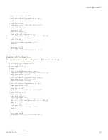


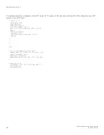


SWRB - BGP configuration
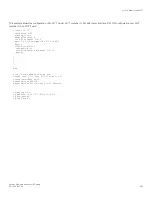
This example presents the BGP configuration for the SWRB cluster device.
!
interface ve 110
ip address 10.110.0.252 255.255.255.0
!
router bgp
local-as 100
neighbor 10.110.0.253 remote-as 100
neighbor 10.110.0.1 remote-as 100
!
S1-SW configuration
This example presents the configuration for the S1-SW device.
!
lag lag_s1_sw static id 60
ports ethernet 1/1/1 to 1/1/2
primary-port 1/1/1
deploy
!
vlan 110 by port
tagged ethernet 1/1/1 to 1/1/2
router-interface ve 110
!
interface ve 110
ip address 10.110.0.1 255.255.255.0
!
router bgp
local-as 100
neighbor 10.110.0.253 remote-as 100
neighbor 10.110.0.252 remote-as 100
!
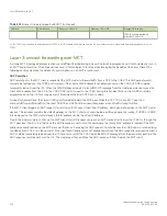
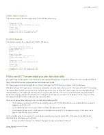
PIM over MCT intermediate router functionality
MCT peers support intermediate router functionality by accepting PIM neighbors on specific interfaces, thus routing multicast traffic as
fully functional PIM devices acting as upstream and downstream routers.
MCT peers support multicast routing (PIM) on Cluster Client Edge Port (CCEP) and Inter-Chassis Link (ICL) interfaces.
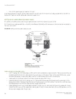
PIM states between MCT peers are synchronized by sending the control packets natively over ICL. The nature of the MCT LAG requires
this. Packets from the MCT client on the CCEP ports are received by only one of the MCT peers. Hence the control packets that are
received natively on the CCEP ports are sent over ICL to synchronize the states. The Join or Prune and Asserts are synchronized to
maintain the Outgoing Interface (OIF) state for the CCEP ports on both peers. For CCEP OIFs created by PIM joins, only one of the
MCT peers forwards the traffic and the other peer drops the traffic.
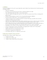
These are the general rules followed for the control packet handling algorithm.
•
Control packets originated from MCT peers will be flooded on MCT VLAN. Exceptions are Assert packets and Join packets
triggered only for ICL OIFs.
•
Control packets received on any port of MCT VLAN are flooded on MCT VLAN.
•
Control packets received on ICL are flooded in a controlled manner on MCT VLAN based on remote CCEP status, that is,
based on whether they are up or down.
Control and data packets received on an ICL port are processed by searching the source MAC of the packet in the MAC table to
determine the packet ingress port as follows:
•
If the source MAC is learned on CCEP port, the packet ingress port will be a CCEP port.
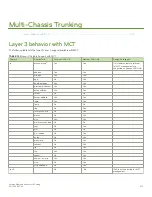
Layer 3 behavior with MCT
FastIron Ethernet Switch Layer 3 Routing
53-1003627-04
581
Summary of Contents for FastIron SX 1600
Page 2: ...FastIron Ethernet Switch Layer 3 Routing 2 53 1003627 04 ...
Page 16: ...FastIron Ethernet Switch Layer 3 Routing 16 53 1003627 04 ...
Page 20: ...FastIron Ethernet Switch Layer 3 Routing 20 53 1003627 04 ...
Page 142: ...FastIron Ethernet Switch Layer 3 Routing 142 53 1003627 04 ...
Page 150: ...FastIron Ethernet Switch Layer 3 Routing 150 53 1003627 04 ...
Page 200: ...FastIron Ethernet Switch Layer 3 Routing 200 53 1003627 04 ...
Page 214: ...FastIron Ethernet Switch Layer 3 Routing 214 53 1003627 04 ...
Page 350: ...FastIron Ethernet Switch Layer 3 Routing 350 53 1003627 04 ...
Page 476: ...FastIron Ethernet Switch Layer 3 Routing 476 53 1003627 04 ...
Page 588: ...FastIron Ethernet Switch Layer 3 Routing 588 53 1003627 04 ...