
•
Ethernet SNAP (also called IEEE 802.3)
The control portions of these packets differ slightly. All IP devices on an Ethernet network must use the same format. Brocade Layer 3
switches use Ethernet II by default. You can change the IP encapsulation to Ethernet SNAP on individual ports if needed.
NOTE
All devices connected to the Layer 3 switch port must use the same encapsulation type.
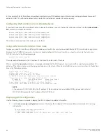
To change the IP encapsulation type on interface 5 to Ethernet SNAP, enter the following commands.
device(config)# interface ethernet 5
device(config-if-e1000-5)# ip encapsulation snap
Syntax:
ip encapsulation
{
snap
|
ethernet_ii
}
Changing the MTU
The Maximum Transmission Unit (MTU) is the maximum length of IP packet that a Layer 2 packet can contain. IP packets that are longer
than the MTU are fragmented and sent in multiple Layer 2 packets. You can change the MTU globally or on individual ports.
The default MTU is 1500 bytes for Ethernet II packets and 1492 for Ethernet SNAP packets.
MTU enhancements
Brocade devices contain the following enhancements to jumbo packet support:
•
Hardware forwarding of Layer 3 jumbo packets - Layer 3 IP unicast jumbo packets received on a port that supports the frame
MTU size and forwarded to another port that also supports the frame MTU size are forwarded in hardware. Previous releases
support hardware forwarding of Layer 2 jumbo frames only.
•
ICMP unreachable message if a frame is too large to be forwarded - If a jumbo packet has the Do not Fragment (DF) bit set,
and the outbound interface does not support the packet MTU size, the Brocade device sends an ICMP unreachable message to
the device that sent the packet.
NOTE
These enhancements apply only to transit traffic forwarded through the Brocade
device.
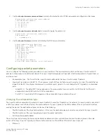
Configuration considerations for increasing the MTU
•
The MTU command is applicable to VEs and physical IP interfaces. It applies to traffic routed between networks.
•
For ICX 7250, ICX 7450, and ICX 7750 devices, the IPv4 and IPv6 MTU values are the same. Modifying one also changes
the value of the other.
•
For ICX 7250, ICX 7450, and ICX 7750 devices, the minimum IPv4 and IPv6 MTU values for both physical and virtual
interfaces are 1280.
•
You cannot use this command to set Layer 2 maximum frame sizes per interface. The global
jumbo
command causes all
interfaces to accept Layer 2 frames.
•
When you increase the MTU size of a port, the increase uses system resources. Increase the MTU size only on the ports that
need it. For example, if you have one port connected to a server that uses jumbo frames and two other ports connected to
clients that can support the jumbo frames, increase the MTU only on those three ports. Leave the MTU size on the other ports
at the default value (1500 bytes). Globally increase the MTU size only if needed.
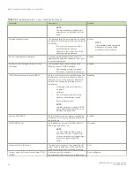
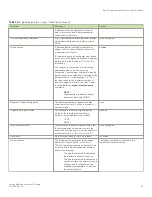
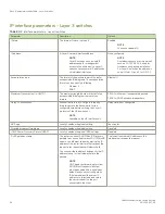
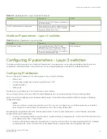
Configuring IP parameters - Layer 3 switches
FastIron Ethernet Switch Layer 3 Routing
46
53-1003627-04
Summary of Contents for FastIron SX 1600
Page 2: ...FastIron Ethernet Switch Layer 3 Routing 2 53 1003627 04 ...
Page 16: ...FastIron Ethernet Switch Layer 3 Routing 16 53 1003627 04 ...
Page 20: ...FastIron Ethernet Switch Layer 3 Routing 20 53 1003627 04 ...
Page 142: ...FastIron Ethernet Switch Layer 3 Routing 142 53 1003627 04 ...
Page 150: ...FastIron Ethernet Switch Layer 3 Routing 150 53 1003627 04 ...
Page 200: ...FastIron Ethernet Switch Layer 3 Routing 200 53 1003627 04 ...
Page 214: ...FastIron Ethernet Switch Layer 3 Routing 214 53 1003627 04 ...
Page 350: ...FastIron Ethernet Switch Layer 3 Routing 350 53 1003627 04 ...
Page 476: ...FastIron Ethernet Switch Layer 3 Routing 476 53 1003627 04 ...
Page 588: ...FastIron Ethernet Switch Layer 3 Routing 588 53 1003627 04 ...