
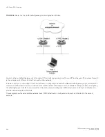
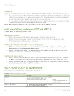
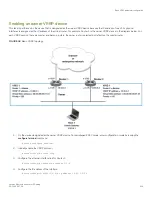
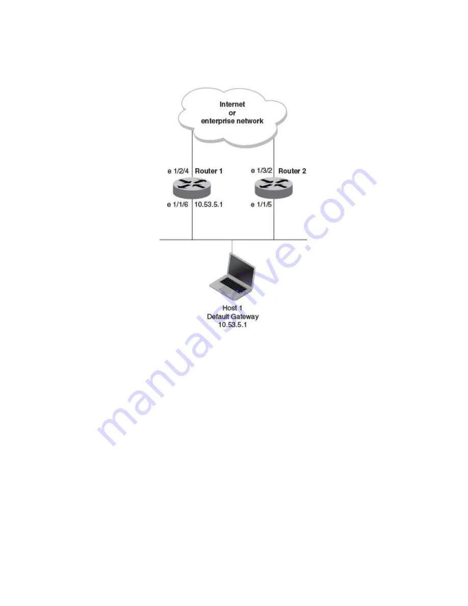
FIGURE 34
Router 1 is the Host1 default gateway but is a single point of failure
Router 1 is the host default gateway out of the subnet. If this interface goes down, Host1 is cut off from the rest of the network. Router 1
is thus a single point of failure for Host1’s access to other networks.
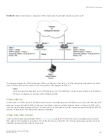
If Router 1 fails, you could configure Host1 to use Router 2. Configuring one host with a different default gateway might not require too
much extra administration. However, consider a more realistic network with dozens or even hundreds of hosts per subnet; reconfiguring
the default gateways for all the hosts is impractical. It is much simpler to configure a VRRP virtual router on Router 1 and Router 2 to
provide a redundant path for the hosts.
The examples show the same sample networks, but a VRRP virtual router is configured on Router 1 and Router 2 in the second
example.
VRRP and VRRP-E overview
FastIron Ethernet Switch Layer 3 Routing
508
53-1003627-04
Summary of Contents for FastIron SX 1600
Page 2: ...FastIron Ethernet Switch Layer 3 Routing 2 53 1003627 04 ...
Page 16: ...FastIron Ethernet Switch Layer 3 Routing 16 53 1003627 04 ...
Page 20: ...FastIron Ethernet Switch Layer 3 Routing 20 53 1003627 04 ...
Page 142: ...FastIron Ethernet Switch Layer 3 Routing 142 53 1003627 04 ...
Page 150: ...FastIron Ethernet Switch Layer 3 Routing 150 53 1003627 04 ...
Page 200: ...FastIron Ethernet Switch Layer 3 Routing 200 53 1003627 04 ...
Page 214: ...FastIron Ethernet Switch Layer 3 Routing 214 53 1003627 04 ...
Page 350: ...FastIron Ethernet Switch Layer 3 Routing 350 53 1003627 04 ...
Page 476: ...FastIron Ethernet Switch Layer 3 Routing 476 53 1003627 04 ...
Page 588: ...FastIron Ethernet Switch Layer 3 Routing 588 53 1003627 04 ...