


NOTE
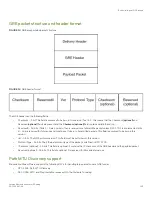
To prevent packet loss after the 24 byte GRE header is added, make sure that any physical interface that is carrying GRE tunnel
traffic has an IP MTU setting at least 24 bytes greater than the tunnel MTU setting. This configuration is only allowed on the
system if the tunnel mode is set to GRE.
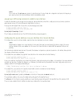
Changing the maximum number of tunnels supported
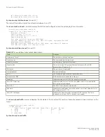
By default, FastIron X Series IPv6 devices support up to 32 GRE tunnels. You can configure the device to support 16 - 64 GRE tunnels.
To change the maximum number of tunnels supported, enter commands such as the following.
device(config)# system-max gre-tunnels 16
Reload required. Please write memory and then reload or power cycle.
device(config)# write memory
device(config)# exit
device# reload
NOTE
You must save the configuration (write memory) and reload the software to place the change into
effect.
Syntax:
system-max
gre-tunnels
number
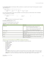
The
number
variable specifies the number of GRE tunnels that can be supported on the device. The permissible range is 16 - 64. The
system-max gre-tunnels
command determines the interface range that is supported for an interface tunnel. For example, if the system-
max value is reduced, it is possible that the configured interfaces may be rejected after a system reload.
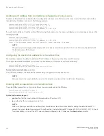
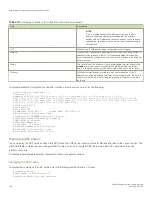
Configuring GRE link keepalive
When GRE tunnels are used in combination with static routing or policy-based routing, and a dynamic routing protocol such as RIP, BGP,
or OSPF is not deployed over the GRE tunnel, a configured tunnel does not have the ability to bring down the line protocol of either
tunnel endpoint, if the far end becomes unreachable. Traffic sent on the tunnel cannot follow alternate paths because the tunnel is always
UP. To avoid this scenario, enable GRE link keepalive, which will maintain or place the tunnel in an UP or DOWN state based upon the
periodic sending of keepalive packets and the monitoring of responses to the packets. If the packets fail to reach the tunnel far end more
frequently than the configured number of retries, the tunnel is placed in the DOWN state.
To enable GRE link keepalive, configure it on one end of the tunnel and ensure the other end of the tunnel has GRE enabled.
NOTE
Keepalives are not supported when a tunnel interface is not within the default-VRF.
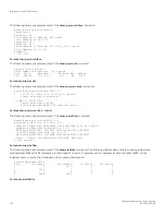
To configure GRE link keepalive, enter commands such as the following.
device(config)# interface tunnel 1
device(config-tnif-1)# keepalive 12 4
These commands configure the device to wait for 4 consecutive lost keepalive packets before bringing the tunnel down. There will be a
12 second interval between each packet. Note that when the tunnel comes up, it would immediately (within one second) send the first
keepalive packet.
Syntax:
[no] keepalive
seconds
retries
Use the
no
form of the command to disable the keepalive option.
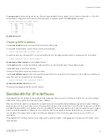
The
seconds
variable specifies the number of seconds between each initiation of a keepalive message. The range for this interval is 2 -
32767 seconds. The default value is 10 seconds.
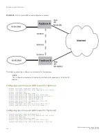
IPv4 point-to-point GRE tunnels
FastIron Ethernet Switch Layer 3 Routing
53-1003627-04
113
Summary of Contents for FastIron SX 1600
Page 2: ...FastIron Ethernet Switch Layer 3 Routing 2 53 1003627 04 ...
Page 16: ...FastIron Ethernet Switch Layer 3 Routing 16 53 1003627 04 ...
Page 20: ...FastIron Ethernet Switch Layer 3 Routing 20 53 1003627 04 ...
Page 142: ...FastIron Ethernet Switch Layer 3 Routing 142 53 1003627 04 ...
Page 150: ...FastIron Ethernet Switch Layer 3 Routing 150 53 1003627 04 ...
Page 200: ...FastIron Ethernet Switch Layer 3 Routing 200 53 1003627 04 ...
Page 214: ...FastIron Ethernet Switch Layer 3 Routing 214 53 1003627 04 ...
Page 350: ...FastIron Ethernet Switch Layer 3 Routing 350 53 1003627 04 ...
Page 476: ...FastIron Ethernet Switch Layer 3 Routing 476 53 1003627 04 ...
Page 588: ...FastIron Ethernet Switch Layer 3 Routing 588 53 1003627 04 ...