background image

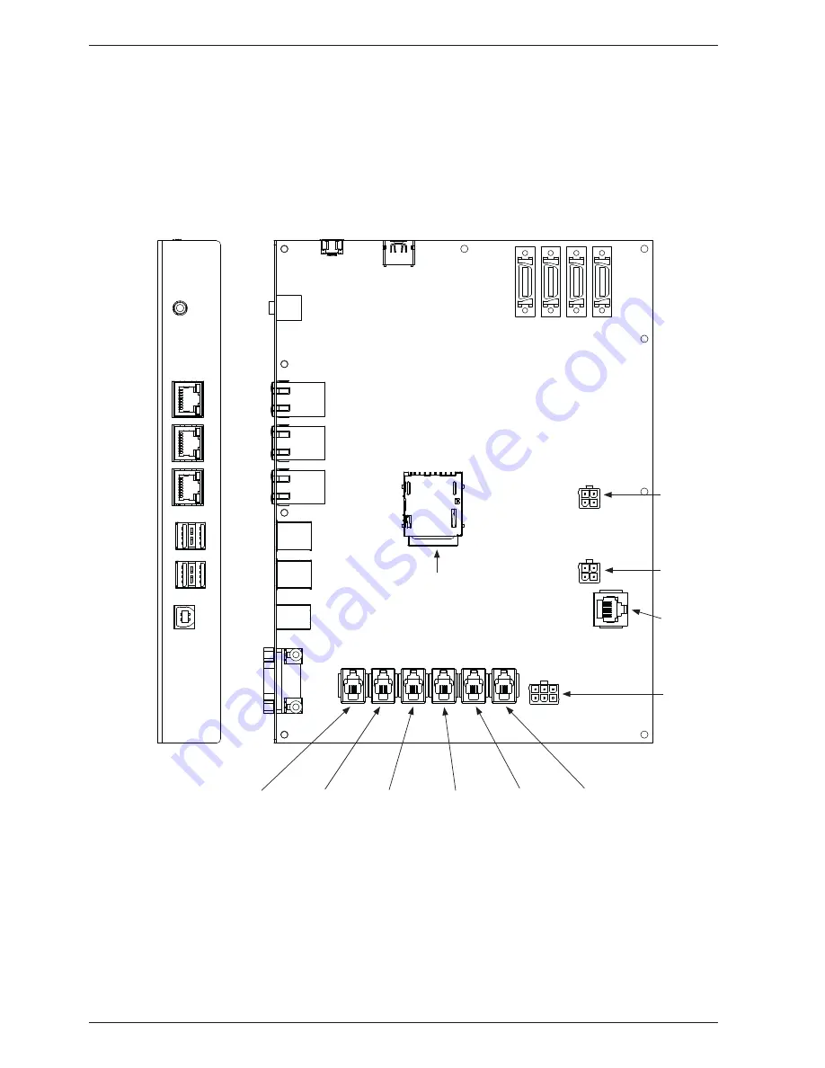
Audio

pre out

Not in use

Not in use

Ethernet

Not in use

Not in use

USB

Power

operator

panel

Signal

operator

panel

Data 

Magnet racks

A    B    C    D

Not

in use

Step

motor
Sync.

External

equip. 

SD memory

card with

software

Spare

sensor 

Cover

sensor 

Beam 

wheel

sensor 

Paper

feed 2

sensor

Paper

feed 1

sensor

Out of

paper

sensor

El-unit

connect.

6.4  Main board - connections

BRAILLO


l


NORWAY AS

B 300 S2

84

Summary of Contents for 300 S2

Page 1: ...User s Guide BRAILLO L NORWAY FOR BETTER BRAILLE AND MORE BRAILLO 300 S2 Rev June 2017 ...

Page 2: ... 2017 Braillo Norway AS ...

Page 3: ...have the ability to change with it Our goal is to manufacture a Braille embosser that when properly maintained by following the instructions in this manual will not only last decades but will also produce Braille that is recognized as the highest quality available We rely on a close cooperation with our customers and we encourage your suggestions for improvements Please take a moment to register y...

Page 4: ...BRAILLO l NORWAY AS B 300 S2 4 ...

Page 5: ... 4 7 Magnet Rack adjustment 50 4 8 Magnet rack refitting and adjusting 52 4 9 Beam and Paper shoes overview 58 4 10 Beam and Papershoes removal and refitting 59 4 11 Beam replacement of short pivot arm 61 4 12 Beam replacement of printing pin 62 4 13 Return spring adjustment 63 4 14 Eccentrics adjustment belt tension 64 4 15 Main sensor wheel adjustment 65 4 16 Paper feed assembly removing 66 4 17...

Page 6: ...BRAILLO l NORWAY AS B 300 S2 6 7 GENERAL INFORMATION 90 7 1 Declaration of conformity 90 7 2 Warranty 91 7 3 Addresses and phone numbers 93 ...

Page 7: ...t tools which come with your printer as well as following the correct procedures which we prescribe in the manual and rein force in our training courses Additionally just as the wrong wrench can ruin a nut using poor quality Braille paper can ruin the printer s pins print shoes and moveable parts by causing them to wear out prematurely Failures due to user negligence of this nature just as repairs...

Page 8: ...ure below Note that the right hand and left hand side are referred to as if you were standing behind the printer facing the opening where the paper is inserted into the printer BRAILLO l NORWAY AS B 300 S2 8 Control panel Paper direction ...

Page 9: ...to ensure long and trouble free operation Temperature should be between 15 30 C 60 86 F and relative humidity between 40 and 60 Maintain a clean environment because dust may clog the Printer especially when combined with high humidity Too low humidity should also be avoided to prevent electrostatic problems Some paper qualities may generate excessive paper dust This should be removed with a vacuum...

Page 10: ...with the following items Power cable for the printer Data cable USB Data cable ethernet shielded A small stack of paper User s guide Tool kit for service and maintenance Test and packing list If any of these items are missing please contact your distributor or Braillo Norway AS Important It is very important that the printer s specified voltage value 230V 10 corresponds with the local mains power ...

Page 11: ...he side panels The side panels can be removed by turning the quarter revolution fasteners counterclockwise Turn counterclockwise 1 4 of a revolution Pull the panel out then a little down BRAILLO l NORWAY AS B 300 S2 11 ...

Page 12: ...s described in section 2 2 Removal of the side panels on page 11 Loose the four bolts a revolution then slide the top a little towards the operator panel side Then lift it straigth up Loosen the four bolts a revolution or so Slide the top a little towards the display side then lift it straigth up BRAILLO l NORWAY AS B 300 S2 12 ...

Page 13: ...al electric contact points observe that the yellow green wire is the grounding earthing wire Also make sure that you are connecting to 230 volts THE PRINTER S MAINS CABLE MUST ALWAYS BE CONNECTED TO GROUND BRAILLO l NORWAY AS B 300 S2 13 Fans outlet Mains inlet Audio pre out NC NC Ethernet NC NC USB Main board Magnetracks DCBA 24V 1A Spare Alarm output Fans on off external equipment Mains 230V 50 ...

Page 14: ...in the Printer so the text file will be transferred to the Printer as fast as the transmission will allow Then the Printer will run until the text buffer is empty See figure below this is a front view of the electrical unit BRAILLO l NORWAY AS B 300 S2 14 Audio pre out NC NC Ethernet NC NC USB Main board Magnetracks DCBA 24V 1A Spare Alarm output Fans on off external equipment Mains 230V 50 60 Hz ...

Page 15: ...rth to position the paper correctly If there is no paper inserted the printer will start an alarm and the display reads Printer Out of paper This is normal and the noise can be silenced by pressing the mute button Note that the Printer will go into sleep mode when it has been inactive for 15 minutes If that hap pens the Printer will wake up if you touch the operating panel or send a file from the ...

Page 16: ...o to the front of the printer 3 The tractors might have to be adjusted sideways to fit to the paper width in use This is done by opening a little lever on the outer side of the tractors then move the tractors so it will fit to the paper width then close the lever again 4 Lock the paper into the tractor feed By using the FINE ADJUST button adjust the paper with respect to the starting mark notch co...

Page 17: ...t counters Advances the paper one sheet Enters the Main menu Moves the paper 0 5 inch forwards Moves the paper 0 5 inch backwards Status information When the printer is powered up you have to press the Accept button to make the printer ready After pressing Accept the window below appears Please see the explanation on the figure below Accept button ...

Page 18: ...or down Move the cursor up Jump back to the previous menu without saving Accept or select button Jump back to the previous menu without saving Accept or select button Increase the value Decrease the value To change a variable setting If a setting can have more than two values the display will look like below Select this to enter sleep mode ...

Page 19: ...es the display will look similar to this The very first time the printer is powered up you have to select the printer model Note The settings set by the operator panel is the default values However when sending a text file from the computer some parameters for this specific job is sent along with the file The parameters that comes with the file will be active during the print job When the job is f...

Page 20: ...h 5 sheets in total Copy 1 1 means there will be just one copy If you would like to pause a print job press the Pause button When the Printer is paused the button will change to Continue Press Continue to continue with the printing If you would like to cancel the rest of the print job press Reset Pause the print job Continue the print job Cancel the rest of the print job ...

Page 21: ...model Warning Set printer Volume Date Print test pattern Embossing disabled Sheet length Line length Embossing disabled Manual running Time Pitch Printer ID Format Event log Event details Speech Acessibility Stepmot current Sheet calibration Ascii tables View Ascii Test sensors Layout Page 1 up down Status software Braille type 6 8 Clear magnet failure GUI style Backlight Line spacing Double line ...

Page 22: ...tween interpoint dots on both sides of the sheet and single sided dots on just one side of the sheet Layout Main Menu Paper Layout Layout Selects between Normal and Z fold mode Normal means that the Braille is organized on the sheet like this Sheet no 1 contains page no 1 and 2 Sheet no 2 contains page no 3 and 4 and so on Z fold is like this Sheet no 1 contains page no 1 and 2 Sheet no 2 contains...

Page 23: ...eps 8 2550 mm Normal setting is Single line spacing Page adjust Main Menu Paper Layout Page adjust This setting will decrease the number of lines on each page from 0 to 9 If the maximum number of lines could be 29 and the setting Max 4 is selected the resulting number of lines will be 25 This function will keep the top margin constant and only the bottom margin will vary The normal setting is 0 Fo...

Page 24: ...omputer cables ethernet and USB Print Test Pattern Main Menu Warning Service diagnostic Warning Print Test Pattern When entering this menu choice a warning window will appear This is to make the user aware that print jobs from the computer will not be printed as long as you are in this sub menu X pattern Will print dots in a x pattern across the sheet useful when searching for missing dots Full ce...

Page 25: ...set the step motor driver X pattern without motor Will activate one and one magnet on the magnet racks Sleep relay Turn the Sleep relay on or off Alarm relay Turn the Alarm relay on or off Spare relay Turn the Spare relay on or off View Log Main Menu Warning Service diagnostic Warning View Log The Printer remembers the different events that has happened and will store them in a log This log can be...

Page 26: ...rtation in the Printer Paper feed 2 This is the second sensor on the paper transportation in the Printer Out of paper This is a sensor that check if there is paper present in the Printer It s fitted on the paper guide on the input side of the Printer Status software Main Menu Warning Service diagnostic Status software A window that will show the Printers current IP address the MAC address and the ...

Page 27: ... Time Main Menu Date and time Time Used to change the time The Sound menu Main Menu Sound Volume Main Menu Sound Volume Volume setting for beep and speech Pitch Main Menu Sound Pitch Sets the pitch level for the beep Speech Main Menu Sound Speech Toggles Speech on or off Accessibility Main Menu Sound Accessibility Toggles Accessibility on or off Beep Main Menu Sound Beep Toggles Beep on or off ...

Page 28: ...and should under normal conditions never be changed However if for some reason the main board on the Printer has been replaced this menu will appear on the first power up Printer ID Main Menu Printer setup Printer ID The Printer has a function to make it possible to identify which Printer has printed a particular Braille book It is done by sending a command along with the Braille book that tells t...

Page 29: ...pt button Now this has become the current table It is also possible to view the translation between characters and dots in the different ASCII tables by pressing the View button Then a list like shown on the right will appear Use the up and down arrows to scroll the list GUI style skin Main Menu Printer setup GUI style skin If any users of this Printer has low vision and or find it a bit difficult...

Page 30: ...ssages and unrecoverable Error messages Messages Magnet failure A defect magnet has been detected during printing The display will say General failure Magnet rack failure and the Printer will stop Please check the log for the details Please check the log for the details Main Menu Warning Service diagnostic Warning View Log To reset the magnet failure message after the repair you have to press the ...

Page 31: ...ume By pressing Continue the Printer will resume the printing from where it was before the error The different recoverable errors are Printer cover open This occurs when one or more panels on the Printer cover are open When the side panels are put back in place the display will change to Press continue to resume Out of paper The Printer has run out of paper and are waiting for paper When paper is ...

Page 32: ...e main motor Press Reset to continue Tip The sensor can be tested manually on Main Menu Warning Service diagnostic Test Sensors Magnet rack failure The magnet self test system has detected problems with a magnet and the printer will stop You may press Reset to continue however you must replace the defect magnet Please check the log for the details Main Menu Warning Service diagnostic Warning View ...

Page 33: ... Warning Print Test Pattern When entering this menu choice a warning window will appear This is to make the user aware that print jobs from the computer will not be printed as long as you are in this sub menu X pattern Will print dots in a x pattern across the sheet useful when searching for missing dots Full cell single sided Prints all six dots on all characters on one side of the sheet useful f...

Page 34: ...nel beside the printer so that you are able to connect the cables However observe that the operator panel is an electrical board and MUST NEVER BE LAID ON A CONDUCTIVE SURFACE If there is a short circuit on the board it might damage the board 4 1 Printing principle The figure below is a very simplified version of the printing mechanism in this printer The four bars across the paper indicates the m...

Page 35: ...ing the parts inside the printing mechanism The printer has been sliced to show more detailed of how it is constructed BRAILLO l NORWAY AS B 300 S2 35 paper b a d c printing pins short pivot arms magnetrack b short pivot arms magnetrack a top view ...

Page 36: ...ust rotate three times to form a complete row of characters Please see figure below First revolution Second revolution Third revolution To be able to print interpoint where both sides of paper are printed simultaneously the back page is offset a little to the right and a little down to fit in between the dots on the front page Please see figure below Front page Back page dashed lines BRAILLO l NOR...

Page 37: ... eccentric shafts Inside each magnet rack there are 42 electrical magnets The magnets are controlling the long pivot arms When a dot is going to be printed the magnet is engaged and the long pivot arm will be drawn against the magnet poles At the same time the beam and the paper shoe will start to move downwards and the short pivot arm will catch the hook of the long pivot arm The beam will contin...

Page 38: ...d and the long pivot arm has been pulled against the magnet The short pivot arm is moving down towards the hook on the long pivot arm Figure C The long pivot arm s hook catch the short pivot arm As the short pivot arm moves further down the printing pin will be forced down into the paper and make the dot BRAILLO l NORWAY AS B 300 S2 38 a b c ...

Page 39: ...General overview Magnet rack B Magnet rack A Main Belt Main Motor Operator panel Electric unit BRAILLO l NORWAY AS B 300 S2 39 ...

Page 40: ... As a start you should run the built in Test Print Depending on what kind of errors you have you should use different tests The essential thing at this stage is to find which magnet rack s is causing the trouble If there is missing dot s use the X pattern to detect which magnet rack s is missing the dot s If there are too many dots use the full cell lines or the test pattern on test print no 4 and...

Page 41: ... paper the reason might be one of the following 1 The sponge list is not pressing enough against the long pivot arm 2 The gap between the two pivot arms is too small 3 The magnet poles have become sticky and this causes the pivot arms to stick to the magnet 4 The long pivot arm 3 does not move properly Control To be sure that you have found the right mechanism after the troubleshooting you can do ...

Page 42: ...pivot arm Support list Magnet Magnet rack board Printing pin Sponge list short pivot arm Sponge list Magnet rack Short pivot arm Pin guide Magnet poles Gap between pivot arms BRAILLO l NORWAY AS B 300 S2 42 ...

Page 43: ...he four screws shown in the figure Magnet racks A B and C are quite easy to reach but to remove magnet rack D it is often best to first remove the paper feed tractor Please see section 4 16 Paper feed assembly removing on page 66 for a description on how to remove the tractor Unscrew the four bolts BRAILLO l NORWAY AS B 300 S2 43 ...

Page 44: ...cks can be considered as the part of the printer that will have the greatest influence on the dot quality so it is very important to know how to deal with them Take the magnet rack out of the printer like described in section 4 3 Magnet rack removal on page 43 Next follow the instructions below Step 1 Remove the two bolts holding the sponge list and then remove the sponge list Sponge list BRAILLO ...

Page 45: ... list and then remove the support list Step 3 Remove the two bolts holding the pivot arm fastener and then care fully remove the pivot arm fastener The magnet rack is now disas sembled Support list Pivot arm fastener BRAILLO l NORWAY AS B 300 S2 45 ...

Page 46: ...re the connections are It does not refer to dot number character number or column number Disassemble the magnet rack like described in section 4 4 Magnet rack disassembly step by step on page 44 Next follow the instructions below Step 1 Remove the five screws holding the list and the list List BRAILLO l NORWAY AS B 300 S2 46 ...

Page 47: ...arrow needle nose pliers Magnet Step 3 Check the magnets internal resistance if you have an ohm meter available The resist ance should be from 185 ohm to 240 ohm Any value outside this range indicates a defect magnet BRAILLO l NORWAY AS B 300 S2 47 ...

Page 48: ...gnet with a new magnet Note the spikes on one of the sides on the magnet These spikes must be oriented the same direction as the rest of the spikes in the magnet rack Note the direction on these spikes BRAILLO l NORWAY AS B 300 S2 48 ...

Page 49: ...ep on page 44 Now use a damp cloth moistened with cleaning alcohol to wipe off the surfaces as described in the figure below Magnet poles on the magnets The support list The iron pieces in the long pivot arms At the back of the long pivot arms Note Never oil grease or lubricate any of the moving parts on a magnet rack This will only attract paper dust and cause clogging BRAILLO l NORWAY AS B 300 S...

Page 50: ...is the travelling distance for the pivot arm And it should be adjusted to about 0 8 mm using a feeler gauge Adjust the nuts on both ends of the magnet rack If the 0 8 mm feeler gauge goes in and the 0 9 mm feeler gauge does not consider the adjustment OK Make sure that the nuts are tight when you are done 0 8 mm feeler gauge Adjust with these nuts BRAILLO l NORWAY AS B 300 S2 50 ...

Page 51: ... sponge list works as a return spring for the pivot arms The correct adjustment is when the sponge list is slightly pressing against the pivot arms but the pivot arms can still move freely Loosen these screws Pivot arms is pressed a little into the sponge BRAILLO l NORWAY AS B 300 S2 51 ...

Page 52: ...he magnet rack horizontally away from the printer so that the magnet rack is touching the horizontal adjustment screws This will ensure that the magnet rack is in exactly the same position as before it was taken off the printer See next section regarding correct adjustment of the magnet racks Note All explanations refer to one magnet rack but these adjustments must be done on all four magnet racks...

Page 53: ...e pressure the pivot arms put on the printing pins This directly affects the shape of the printed dots To be able to adjust the magnet rack correctly it is necessary to put the printer in printing posi tion This is done by rotating the main belt by hand until the arrows at the ends of the shaft are point ing exactly 180 degrees away from each other It is possible to get the mechanism to balance in...

Page 54: ...ding the magnet rack Then unscrew the horizontal adjustment screw a little Now slide the magnet rack outward from the printer so it touches the horizontal adjustment screws again Then tighten the four fastening screws just a little so the magnet rack is held firmly in place but is still able to move Use the horizontal adjustment screw to move the magnet rack closer to the printer If this is done i...

Page 55: ...to find the correct level of vertical adjustment is to first decrease the pressure so the dots will be very faded and weak Then readjust the pressure up in small steps until the dot quality is satisfactory By doing this you can make sure that you are running the printer with just enough pressure to make good dots but not so much pressure that the printer will be worn damaged From our experience we...

Page 56: ...ning the upper nut and then tighten the lower Do this on both ends so the magnet rack stays levelled Note Adjust in small steps only 1 4 of a revolution at a time Then test the Braille quality BRAILLO l NORWAY AS B 300 S2 56 ...

Page 57: ...ly observe that magnet rack A and B must be moved upwards to increase the pressure and magnet rack C and D must be moved downwards to increase the pressure Moving away from the paper increases pressure BRAILLO l NORWAY AS B 300 S2 57 paper b a d c ...

Page 58: ...ease see the figures below UPPER UPPER LOWER LOWER Upper Beam Upper Paper shoe Lower Paper shoe Lower Beam Adiprene springs Return spring blue Return spring green Plastic shims BRAILLO l NORWAY AS B 300 S2 58 Paper moves in this direction ...

Page 59: ...per guide 3 Remove the paper feed tractor 4 Remove the top frame 5 Remove magnet rack A and B 1 Remove the belt This is done by loosening the bolts for the belt tensioner When this is done the belt can be lifted off the upper cogwheel Please see figure to the right Loosening these two bolts to take off the belt 2 Remove inside paper guide BRAILLO l NORWAY AS B 300 S2 59 Inside paper guide ...

Page 60: ...e the top frame Unscrew the bolts as indicated on the figure below and then lift the frame carefully upwards and remove Place aside 5 Remove magnet rack A and B 3 Remove the paper feed tractor Please see section 4 16 Paper feed assembly remov ing on page 66 for a description on how to remove the tractor BRAILLO l NORWAY AS B 300 S2 60 When assembling the mark ing UPPER and LOWER on the papershoes ...

Page 61: ...ivot arms there are 21 pcs on each shaft 2 Pull out the shaft and replace the short pivot arm s Assembly is done in reverse order Note When putting the short pivot arms back into the beam be sure that the printing pins are hanging vertically like in the figure This is to make room for the short pivot arm BRAILLO l NORWAY AS B 300 S2 61 ...

Page 62: ...te Before the parts are separated make sure that the beam is held with the printing pins hanging down Place the pin guide with the pins on a table Do not turn it upside down or all the pins will fall out Now the defect printing pin can be replaced Assembly is done in reverse order BRAILLO l NORWAY AS B 300 S2 62 ...

Page 63: ...orrect position See the marks at the end of the shafts the arrows must point directly towards each other like in the figure below Then the springs can be adjusted to the correct length i e 68 mm Note It is critically that the length of these two return springs is 68 mm BRAILLO l NORWAY AS B 300 S2 63 68mm 68mm ...

Page 64: ...owards each other See figure below If the marks are not aligned like in the figure it might be necessary to move the belt a notch or two on one of the wheels This is done by loosening the belt tightening wheel 2 again and then lift the belt up from the big wheel and move it a notch on the wheel Then tighten the belt 2 1 BRAILLO l NORWAY AS B 300 S2 64 Direction of rotation When pushing in by hand ...

Page 65: ...ition A in the figure below i e the mark in the middle of the opening in the wheel is placed just opposite the sensor If the timing wheel is not in it s correct position it must be adjusted Keep the shafts in this position while loosen screw B holding the timing wheel Turn the timing wheel until the inductive sensor is placed just opposite the mark in the middle of the opening in wheel Then fasten...

Page 66: ...moving The paper feed assembly can be removed by loosening four nuts There is no need to remove the nuts completely just loose them and then lift the assembly up and pull out Loose these four nuts BRAILLO l NORWAY AS B 300 S2 66 ...

Page 67: ...een the paper parking position and where the stepping motor is parking Loosen the paper feed shaft by unscrewing the two left hand screws B on the sensor wheel Note Do not loosen the screws for the stepping motor shaft Put a sheet of paper into the tractors on the paper feed Now the tractor feed shaft can be turned forward or backward until the paper is in the desired position Tighten the screws B...

Page 68: ...ere the cable enters the sensor Inside the sensor is a little LED lamp that will be lit if a magnetic object is in front of the sensor The light comes out through some transparent plastic around the cable So by having the power turned on and at the same time turning the shafts the light should go on and off When replacing adjusting the sensors the gap between the timing wheel and the sensors can b...

Page 69: ... it functions like this An infrared lamp is sending light downward If there is paper present the light will be reflected back and detected by a photo transistor If the sensor is defective it must be replaced It can be done like this Take the paper guide out of the printer Unscrew first the screws A and then B Now the sensor is loose The assembly is done in reverse order Paper sensor BRAILLO l NORW...

Page 70: ...g pivot arms pressed against the support list When putting the magnet racks back in check all the magnet rack adjustments Check if the printing pins move freely and if not clean the printing pin guide Every 1000 hours or twelve months All of the 500 hours or six months maintenance Check all four sponges for the short pivot arms the sponge should be able to keep the short pivot arm pressed all to t...

Page 71: ...0 running hours or approximately once a year Lubricate all items marked 1 on the figure below These are the only locations in the printer grease may be applied Use a universal grease with molybdensulfid BRAILLO l NORWAY AS B 300 S2 71 1 1 1 1 ...

Page 72: ... magnet rack Pos Name Quantity per rack 1 Sponge list magnet rack 1 2 Magnet rack 1 3 Support list magnet rack 1 4 Shaft long pivot arm 1 5 Pivot arm long 42 6 Electronic board magnet rack 1 7 Magnet 42 8 Guide list magnet rack 1 BRAILLO l NORWAY AS B 300 S2 72 ...

Page 73: ...tity per beam 1 Stroke ball bearing Ø20 2 2 Beam upper or lower 1 3 Fastener for short pivot arm shaft 2 4 Sponge list for short pivot arm 2 5 Pin guide 1 6 Short pivot arm 84 7 Printing pin length 64 5 mm 84 8 Shaft short pivot arm 4 BRAILLO l NORWAY AS B 300 S2 73 ...

Page 74: ...e UPPER Parts paper shoe upper or lower Pos Name Quantity per shoe 1 Retaining ring 4 2 Stroke ball bearing Ø20 2 3 Spacer 2 4 Paper shoe upper or lower 1 5 Plastic shims 4 BRAILLO l NORWAY AS B 300 S2 74 1 2 3 4 5 ...

Page 75: ... 4 Paper feed Parts paper feed Pos Name Quantity 1 Paper feed tractor 2 2 Paper feed sensor no 1 1 3 Paper feed sensor no 2 1 4 Timing wheel 1 5 Stepping motor 1 BRAILLO l NORWAY AS B 300 S2 75 1 3 4 5 2 ...

Page 76: ...lt 540 L 1 3 Cog wheel 40 L 100 2 4 Belt tensioner 1 5 Cog wheel 12 L 100 1 BRAILLO l NORWAY AS B 300 S2 76 1 2 3 4 5 How to get the cog wheel off the shaft Unscrew the two screws Place one of the screws in the third hole and screw it inwards until the wheel is loose Direction of rotation ...

Page 77: ...Parts shaft exploded Pos Name Quantity per shaft 1 Main bearing with housing 2 2 Nut KM5 2 3 Bearing outer eccentric 6205 2Z 2 4 Shaft 1 Shaft exploded view BRAILLO l NORWAY AS B 300 S2 77 1 2 3 4 ...

Page 78: ...tom frame Parts top and bottom frame exploded Pos Name Quantity per frame 1 Locking ring Ø22 4 2 Stroke ball bearing Ø12 2 3 Frame 1 4 Spacer Ø22 2 5 Push rod ceramic Ø12X56 2 1 2 3 4 5 BRAILLO l NORWAY AS B 300 S2 78 ...

Page 79: ...Frame complete BRAILLO l NORWAY AS B 300 S2 79 ...

Page 80: ...r 8 dot Paper weight 120 180 g m recommended 150 g m Printing speed 300 characters per second or a maximum of 900 printed pages per hour based on a 12 inch sheet Electrical Voltage Single phase 230V 10 50 60 Hz Current Approximately 5 A max Fuse Printer 10 A Power Approximately 1000 W max Communication with the computer USB Ethernet Environment Temperatures 15 30 C 60 86 F Rel Humidity 40 60 Measu...

Page 81: ...rd connector Magnet rack power connector 6 2 Electric unit overview The electric unit is placed on the base plate of the Printer and contains connections fuses and power supply Note that you must disconnect the mains when working on this unit BRAILLO l NORWAY AS B 300 S2 81 ...

Page 82: ...rews Lift the lid upwards 6 3 How to replace fuses The fuses are placed on a PCB inside the electric unit See figures below for how to open the box Remember to disconnect the mains cable first BRAILLO l NORWAY AS B 300 S2 82 ...

Page 83: ...e 2 1 AT M rack A 3 15 AT M rack B 3 15 AT M rack C 3 15 AT M rack D 3 15 AT The fuses Note that the two mains fuses is placed under transparent lids All the fuses are 5 x 20 mm and can be of glass or ceramic type BRAILLO l NORWAY AS B 300 S2 83 ...

Page 84: ...gnal operator panel Data Magnet racks A B C D Not in use Step motor Sync External equip SD memory card with software Spare sensor Cover sensor Beam wheel sensor Paper feed 2 sensor Paper feed 1 sensor Out of paper sensor El unit connect 6 4 Main board connections BRAILLO l NORWAY AS B 300 S2 84 ...

Page 85: ... command on the other pages it will be skipped All page formatting which is done on the front page will also format the back of the same sheet It is for example not possible to have 8 dot Braille on the front page and 6 dot on the back page It is possible to mix 6 and 8 dot Braille however as long as it is done on two differ ent sheets An overview of the different escape sequences ESC A nn Sheet l...

Page 86: ...10 5 027 065 050 049 1B 41 32 31 11 0 027 065 050 050 1B 41 32 32 11 5 027 065 050 051 1B 41 32 33 12 0 027 065 050 052 1B 41 32 34 12 5 027 065 050 053 1B 41 32 35 13 0 027 065 050 054 1B 41 32 36 13 5 027 065 050 055 1B 41 32 37 14 0 027 065 050 056 1B 41 32 38 Default is 12 inches Line length ESC B nn Line length nn can be from 10 to 42 characters Char ASCII HEX 10 027 066 049 048 1B 42 31 30 1...

Page 87: ...7 077 048 053 1B 4D 30 35 6 1 9050 027 077 048 054 1B 4D 30 36 7 2 2225 027 077 048 055 1B 4D 30 37 8 2 5400 027 077 048 056 1B 4D 30 38 9 2 8575 027 077 048 057 1B 4D 30 39 10 3 1750 027 077 049 048 1B 4D 31 30 11 3 4925 027 077 049 049 1B 4D 31 31 12 3 8100 027 077 049 050 1B 4D 31 32 13 4 1275 027 077 049 051 1B 4D 31 33 14 4 4450 027 077 049 052 1B 4D 31 34 15 4 7625 027 077 049 053 1B 4D 31 3...

Page 88: ...0000 027 084 048 048 1B 54 30 30 1 0 6350 027 084 048 049 1B 54 30 31 2 1 2700 027 084 048 050 1B 54 30 32 3 1 9050 027 084 048 051 1B 54 30 33 4 2 5400 027 084 048 052 1B 54 30 34 5 3 1750 027 084 048 053 1B 54 30 35 6 3 8100 027 084 048 054 1B 54 30 36 7 4 4450 027 084 048 055 1B 54 30 37 8 5 0800 027 084 048 056 1B 54 30 38 9 5 7150 027 084 048 057 1B 54 30 39 10 6 3500 027 084 049 048 1B 54 31...

Page 89: ...ed printing of the Printer This command makes the Printer to start print ing the rest of the text After this the paper position will be the same as it had when this volume of text was started Then page no 1 on the next volume will start out correctly There will always be at least one blank sheet of paper between the volumes of text when finishing each volume with a Software Form Feed ASCII HEX Sof...

Page 90: ...7 GENERAL INFORMATION 7 1 Declaration of conformity BRAILLO l NORWAY AS B 300 S2 90 ...

Page 91: ...rth quake etc damaging the product Should a replacement part be required please do the following Send us a Warranty request form Please refer to the next page to see the actual form The form can also be found on the enclosed CD ROM After completing the form please return it to Braillo Norway A S by e mail fax or regular mail When received the parts will be shipped as soon as possible What to do wi...

Page 92: ...ment is not returned within two weeks of origination We will assume that it is not required and it will be cancelled Internal use only Garanti Kunde belastes Kommentarer på reparasjon Reason for return Comments Return to Braillo Norway A S Wessel veg 100 7502 Stjørdal Norway Phone number 47 74 84 04 40 Fax number 47 74 84 04 41 E mail service braillo com BRAILLO l NORWAY AS B 300 S2 92 ...

Page 93: ... 20 Tønsberg Mail P O Box 447 3101 Tønsberg Norway Phone 47 33 00 28 70 Telefax 47 33 00 28 71 e mail sales braillo com Service Braillo Norway AS Office Wessels veg 100 Stjørdal Mail P O Box 93 7501 Stjørdal Norway Phone 47 74 84 04 40 Telefax 47 74 84 04 41 e mail service braillo com BRAILLO l NORWAY AS B 300 S2 93 ...

Reviews: