background image

34/56 Installation

Bosch Rexroth AG

, A2FM/A2FE/A2FMT Series 70, RE 91071-01-B/06.2018

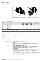
2

4

6

8

7

5

3

1

2)

2)

Y

1)

B1

B2

B3

Y

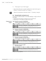
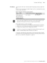
B4

1)

SAE flange

2)

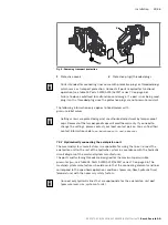
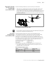
Tacking screw (M6 x 1, length = B1 + B2, DIN 912)

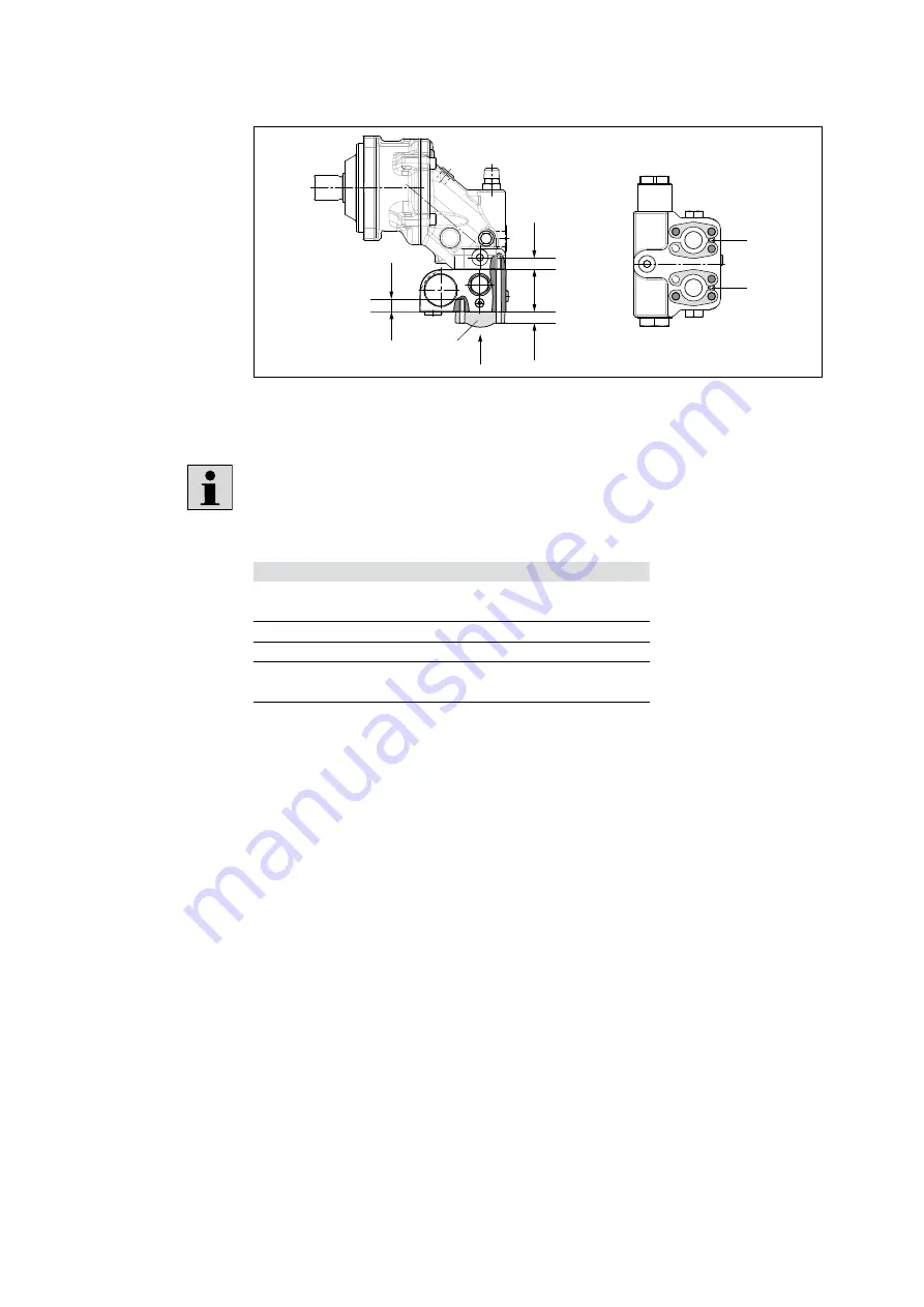
Fig. 11: Mounting the counterbalance valve

The SAE flange and corresponding mounting bolts are not included in the scope 
of delivery.

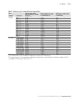
Table 14: Thread sizes and dimensions

Size

56, 63

80, 90

Dimension B1

1)

M10 x 1.5
17 deep

M12 x 1.75
18 deep

Dimension B2

68 mm

68 mm

Dimension B3

Customer-specific (flange-dependent)

Dimension B4

M10 x 1.5
15 deep

M12 x 1.75
16 deep

DIN 13 fastening thread For DIN 13 mounting bolts, we recommend checking the tightening torque 
on a case-by-case basis according to VDI 2230 Edition 2003.

1) 

Min. required thread reach 1 x Ø of thread

View

Summary of Contents for Rexroth 70 Series

Page 1: ...Instruction manual RE 91071 01 B 06 2018 Replaces 03 2015 English Axial piston fixed motor A2FM A2FE A2FMT Series 70 ...

Page 2: ...concerning a certain condition or suitability for a certain application can be derived from our information The information given does not release the user from the obligation of own judgment and verification It must be remembered that our products are subject to a natural process of wear and aging The cover shows an example application The product delivered may differ from the image on the cover ...

Page 3: ...18 5 1 Performance description 18 5 2 Product description 18 5 2 1 Axial piston unit layout 18 5 2 2 Functional description 19 5 3 Product identification 19 6 Transport and storage 20 6 1 Transporting the axial piston unit 20 6 1 1 Transporting by hand 21 6 1 2 Transporting with a lifting device 21 6 2 Storing the axial piston unit 22 7 Installation 25 7 1 Unpacking 25 7 2 Installation conditions ...

Page 4: ...tandstill 42 9 Operation 43 10 Maintenance and repair 44 10 1 Cleaning and care 44 10 2 Inspection 45 10 3 Maintenance 45 10 4 Repair 46 10 5 Spare parts 46 11 Removal and replacement 47 11 1 Required tools 47 11 2 Preparing for removal 47 11 3 Removal 47 11 4 Preparing the components for storage or further use 47 12 Disposal 48 13 Extension and conversion 48 14 Troubleshooting 49 14 1 How to trou...

Page 5: ...llation drawing Contains the outer dimensions all connections and the hydraulic schematic of your A2FM A2FE or A2FMT axial piston fixed motor Please request the installation drawing from your contact at Bosch Rexroth Installation drawing Axial piston fixed motor A2FM axial piston plug in motor A2FE series 70 Contains the permissible technical data 91071 Data sheet Axial piston fixed motor A2FMT se...

Page 6: ...s attention to the danger Signal word identifies the degree of the danger Type and source of danger indicates the type and source of the danger Consequences describes what occurs if safety instructions are not complied with Precautions states how the danger can be avoided Table 2 Danger classes as defined in ANSI Z535 6 Warning sign signal word Meaning DANGER Identifies a dangerous situation that ...

Page 7: ...ion The designation axial piston unit is used from this point forward as a generic term for the A2FM axial piston fixed motor A2FE axial piston plug in motor or A2FMT axial piston fixed motor 1 3 4 Abbreviations This manual uses the following abbreviations Table 5 Abbreviations Abbreviation Meaning ATEX EC directive on explosion protection Atmosphère explosible DIN Deutsches Institut für Normung G...

Page 8: ... is intended for the following use The A2FM and A2FE axial piston units are only approved as hydraulic motors in hydrostatic drives The A2FMT axial piston unit is only approved as a hydraulic motor for hydrostatic drum drives in a closed circuit in concrete mixer trucks Observe the technical data the application and operating conditions and the performance limits as specified in data sheet 91071 9...

Page 9: ...n this manual require a basic understanding of mechanics electricity and hydraulics as well as familiarity with associated technical terms For transporting and handling the product additional familiarity with the use of lifting devices and lifting accessories is required In order to ensure safe use these activities should only be performed by qualified personnel or an instructed person under the d...

Page 10: ...levance to safety unexpected operating conditions may occur in the application which could result in personal injury or property damage For this reason only use the product in safety relevant applications if this use is expressly indicated and approved in the product documentation e g in explosion protection applications or in safety related parts of a control system functional safety Only commiss...

Page 11: ... g crushing or fracture or damage to the product Make sure that the load bearing capacity of the lifting device is sufficient to safely bear the weight of the axial piston unit Never stand or put your hands under a suspended load Make sure the unit remains stable during transport Wear your personal protective equipment e g safety goggles safety gloves suitable working clothes safety shoes Use suit...

Page 12: ... contamination e g impure hydraulic fluid This can result in limitation or loss of the load holding function in lifting winches Check whether the application on your machine requires additional safety measures in order to keep the load in a safe position If necessary make sure that these are properly implemented CAUTION High noise development during operation Risk of hearing damage or hearing loss...

Page 13: ...stream or is swallowed Escaping hydraulic fluid due to leakage from machine system components Risk of burning and injury due to escaping hydraulic fluid jet Depressurize the relevant machine system component and repair the leak Never attempt to block or seal the leak or hydraulic fluid jet with a cloth Danger from improper handling Risk of slipping Risk of slipping on wet surfaces when climbing on...

Page 14: ...equate lubrication Product can be damaged or destroyed Never operate the axial piston unit with insufficient hydraulic fluid Specifically make sure that the rotary group has sufficient lubrication When commissioning a machine system make sure that the housing area and the working lines of the axial piston unit are filled with hydraulic fluid and remain filled during operation Avoid air inclusions ...

Page 15: ...g to minimize solid particle contamination and water in the hydraulic system Improper cleaning Product can be damaged Close all openings with appropriate protective covers in order to prevent cleaning agents from entering the hydraulic system Never use solvents or corrosive cleaning agents Use only water and if necessary a mild cleaning agent to clean the axial piston unit Do not point a high pres...

Page 16: ...id is spilled Observe the safety data sheet for the hydraulic fluid and the specifications provided by the system manufacturer Danger from hot components Nearby products can be damaged Components that heat up e g solenoids can cause damage to nearby products if they are too close When installing the axial piston unit check the distances to nearby products to ensure that they are not damaged The wa...

Page 17: ...T Series 70 Bosch Rexroth AG 4 Scope of delivery 1 2 2 Fig 1 Axial piston unit The scope of delivery includes the following Axial piston unit as per order confirmation The following parts come assembled on the unit Protective covers 1 Protective threaded plugs 2 ...

Page 18: ...rcuit hydrostatic drum drives in concrete mixer trucks In axial piston units with a bent axis design the pistons 2 are arranged at an angle to the drive shaft 1 The pistons rest directly on the drive shaft where they generate torque depending on the pressure In an open circuit the hydraulic fluid flows from the reservoir to the hydraulic pump where it is transported to the hydraulic motor The hydr...

Page 19: ...ressure sides The output speed is proportional to the inward flow and inversely proportional to the displacement of the hydraulic motor 5 3 Product identification The axial piston unit can be identified by the name plate The following example shows an A2FM name plate CNR MNR SN FD Rotation DE 89275 Elchingen Made in Germany X1234567890Y R90XXXXXXX SC X 12345678 Rexroth 17W18 m XXX kg 7202 Typ A2FM...

Page 20: ...n be found in the installation drawing request if necessary Height mm Depth mm Table 7 Dimensions and weights for A2FMM A2FEM Nominal pressure 400 bar max pressure 450 bar Size 45 56 63 80 90 Weight kg 17 17 17 23 23 Width mm Dimensions vary by equipment The values applicable for your axial piston unit can be found in the installation drawing request if necessary Height mm Depth mm Table 8 Dimensi...

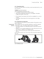
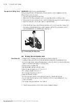
Page 21: ...g to prevent it from being damaged 6 1 2 Transporting with a lifting device For transporting the axial piston unit can be connected to a lifting device via an eye bolt or a lifting strap The axial piston unit can be transported suspended from an eye bolt screwed into the drive shaft as long as only outward pulling axial forces are applied For all female threads use a stud end from the same system ...

Page 22: ...ed from assembled parts see Fig 5 Fig 5 Transporting with lifting strap 6 2 Storing the axial piston unit Storage areas should be free of corrosive materials and gases To prevent damage to the seals do not operate ozone forming equipment e g mercury vapor lamps high voltage equipment electric motors sources of electrical sparks or electrical discharge in storage areas Storage areas should be dry R...

Page 23: ...he warranty will be voided if the requirements and storage conditions are not observed or after expiration of the max storage time see Table 10 What to do once the max storage time elapses 1 Check the entire axial piston unit for damage and corrosion prior to installation 2 Perform a test run to check the axial piston unit for proper function and leaks 3 If storage time exceeds 24 months replace t...

Page 24: ...it see chapter 10 1 Cleaning and care on page 44 2 Drain the axial piston unit 3 For storage periods up to 12 months Coat the inside of the axial piston unit with mineral oil and fill with about 100 mL of mineral oil For storage periods up to 24 months Fill the axial piston unit with VCI 329 corrosion protection 20 mL Fill through the drain port T1 or T2 see chapter 7 4 Installing the axial piston...

Page 25: ...he axial piston unit Check the axial piston unit for transport damage and completeness see chapter 4 Scope of delivery on page 17 Dispose of the packaging in accordance with the regulations in your country 7 2 Installation conditions The installation position and location of the axial piston unit essentially determine how it is installed and commissioned such as when filling and air bleeding the a...

Page 26: ...e function and service life of the axial piston unit Use fiber free cloths for cleaning Use suitable mild cleaning agents to remove lubricants and other heavy contamination Do not allow cleaning agents to enter into the hydraulic system 7 3 Installation position The axial piston unit can be installed in the following positions The pipeline routing shown illustrates the basic layout 7 3 1 Below res...

Page 27: ...he A2FE and A2FMT with the drive shaft up Recommendation for installation position 8 drive shaft up A check valve in the drain line cracking pressure 0 5 bar can prevent the housing area from draining T1 L1 ht min hmin T2 L1 ht min hmin T1 L1 ht min hmin T2 R L1 0 5 bar ht min hmin 5 6 7 8 T1 T2 Highest drain port ht min Min required immersion depth 200 mm L1 Filling air bleeding Notice L1 is part...

Page 28: ...4 Check the permissible direction of rotation of the axial piston unit on the name plate and make sure that this corresponds to the direction of rotation of the intended motor function L R W Fig 8 Direction of rotation W Bi directional can rotate counterclockwise and clockwise L Counterclockwise R Clockwise The direction of rotation as indicated on the name plate determines the direction of rotati...

Page 29: ...e clutch hub on the drive shaft of the axial piston unit by striking it 1 Install the specified clutch half on the drive shaft of the axial piston unit according to the instructions of the clutch manufacturer The drive shaft of the axial piston unit is equipped with a female thread Use this female thread to pull the clutch element onto the drive shaft The size of the female thread can be seen in t...

Page 30: ...rication Fasten the axial piston unit at the installation location No gearing forces higher than the maximum permissible axial and radial forces should act on the shaft if necessary support the gear wheel at the gearbox output separately 7 4 6 Completing installation 1 Remove any installed transport screws Caution Operation with protective plugs Operating the axial piston unit with protective plug...

Page 31: ... of the tamper proof caps will void the warranty If you need to change the settings please contact your local contact person You can find their contact information under www boschrexroth com adresses 7 4 7 Hydraulically connecting the axial piston unit The machine system manufacturer is responsible for sizing the lines Connect the axial piston unit to the rest of the hydraulic system in accordance...

Page 32: ...al piston unit is equipped with installed screw fittings do not remove them Screw the stud end of the fitting directly into the installed fitting Axial piston units are used in application areas that use the metric system as well as the Anglo American imperial and the Japanese measuring system JIS Japan Industrial Standard Various kinds of seals are also used The system of units the kind of seal a...

Page 33: ...alance valve comes mounted to the motor with two tacking screws transport lock Do not remove the tacking screws when connecting the working lines If the counterbalance valve and motor are delivered separately the counterbalance valve must first be fastened to the motor housing using the tacking screws provided The counterbalance valve is finally mounted to the motor by screwing on the SAE flange w...

Page 34: ... are not included in the scope of delivery Table 14 Thread sizes and dimensions Size 56 63 80 90 Dimension B11 M10 x 1 5 17deep M12 x 1 75 18deep Dimension B2 68 mm 68 mm Dimension B3 Customer specific flange dependent Dimension B4 M10 x 1 5 15deep M12 x 1 75 16deep DIN 13 fastening thread For DIN 13 mounting bolts we recommend checking the tightening torque on a case by case basis according to VD...

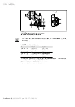
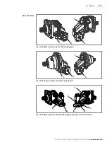
Page 35: ...eries 70 Bosch Rexroth AG B T2 A T1 Fig 12 A2FM port overview lateral SAE working ports B T2 A T1 Fig 13 A2FE port overview lateral SAE working ports A B MA MB S1 T1 T2 Fig 14 A2FM port overview bottom SAE working ports and pressure relief valve Port overview ...

Page 36: ...p this in mind when selecting measuring devices and fittings 3 Depending on the installation position T1 or T2 must be connected see chapter 7 3 Installation position on page 26 O Must be connected comes plugged X Plugged in normal operation The following tightening torques apply Fittings Observe the manufacturer s specifications regarding the tightening torques of the fittings used Female threads...

Page 37: ... mm M27 2 330 Nm 135 Nm1 12 mm M33 2 540 Nm 225 Nm1 17 mm M42 2 720 Nm 360 Nm1 22 mm M48 2 900 Nm 400 Nm1 24 mm ISO 11926 5 16 24 UNF 2B 10 Nm 7 Nm 1 8 in 3 8 24 UNF 2B 20 Nm 10 Nm 5 32 in 7 16 20 UNF 2B 40 Nm 18 Nm 3 16 in 9 16 18 UNF 2B 80 Nm 35 Nm 1 4 in 3 4 16 UNF 2B 160 Nm 70 Nm 5 16 in 7 8 14 UNF 2B 240 Nm 110 Nm 3 8 in 1 1 16 12 UN 2B 360 Nm 170 Nm 9 16 in 1 5 16 12 UN 2B 540 Nm 270 Nm 5 8 ...

Page 38: ... plugged with threaded plugs 5 Tighten the fittings correctly note tightening torques Mark all correctly tightened fittings e g with a permanent marker 6 Check all pipes and hose lines and every combination of connecting pieces couplings or connecting points with hoses or pipes to ensure they are in safe working condition Relationship between direction of rotation and flow direction Clockwise rota...

Page 39: ...ed product Risk of injury and property damage Make sure that all electrical and hydraulic ports are connected or plugged Only commission a completely installed fully functioning product with original accessories from Bosch Rexroth 8 1 Initial commissioning During all commissioning work on the axial piston unit observe the general safety instructions and intended use detailed in chapter 2 Safety in...

Page 40: ... as defined in ISO 4406 At a hydraulic fluid viscosity of less than 10 mm s e g due to high temperatures during short term operation at the drain port a min cleanliness level of 19 17 14 as defined in ISO 4406 is required For permissible viscosities and temperatures see data sheets 91071 and 91072 1 Place a drip tray under the axial piston unit to collect any hydraulic fluid that may leak Notice C...

Page 41: ... test to ensure that the hydraulic system is sealed and can withstand the max pressure 5 At max working pressure check the case drain pressure at port T1 or T2 Refer to data sheets 91071 and 91072 for the permissible value 8 1 3 Performing a functional test WARNING Improperly connected axial piston unit Mixing up the ports will lead to malfunctions e g lift instead of lower and associated hazards ...

Page 42: ...hours Volumetric and mechanical hydraulic efficiency is also greater until the running in phase of about 10 operating hours is concluded To ensure that contamination in the hydraulic system does not damage the axial piston unit Bosch Rexroth recommends the following after the running in phase After the running in phase have a hydraulic fluid sample analyzed for the required cleanliness level Chang...

Page 43: ...no settings or changes during operation For this reason this chapter of the manual does not contain any information on adjustment options Use the product only within the performance range specified in the technical data The machine system manufacturer is responsible for the proper planning of the hydraulic system and its control system ...

Page 44: ...electrical system of the axial piston unit Do not point a high pressure cleaner at sensitive components e g shaft seal electrical connections and components For cleaning and care of the axial piston unit observe the following Check whether all seals and plug in connections are securely seated to ensure that no moisture can penetrate into the axial piston unit during cleaning Use only water and if ...

Page 45: ...d faults on the machine system and rectify them This is why Bosch Rexroth recommends always keeping the axial piston unit and system clean Daily Check axial piston unit for unusual noise development Daily Check fastening elements for tight seating All fasteners have to be checked when the hydraulic system is switched off depressurized and cooled down Monthly 10 3 Maintenance The axial piston unit ...

Page 46: ...are parts Spare parts that do not meet the technical requirements specified by Bosch Rexroth can cause injury and property damage Only use original spare parts from Rexroth to repair the Rexroth axial piston units otherwise the functional reliability of the axial piston unit cannot be guaranteed and the warranty will be voided The spare parts lists for axial piston units are order specific When or...

Page 47: ... Proceed as follows to remove the axial piston unit 1 Make sure you have the appropriate tools and wear personal protective equipment 2 Allow the axial piston unit to cool down until it can be removed without danger 3 For below reservoir installation before removing the axial piston unit from the entire system seal the connection to the reservoir or drain the reservoir 4 Place a drip tray under th...

Page 48: ...ations in your country 3 Dispose of the hydraulic fluid in accordance with the regulations of your country Also observe the applicable safety data sheet for the hydraulic fluid 4 Disassemble the axial piston unit into its constituent parts for proper recycling 5 For example separate into the following Castings Steel Aluminum Non ferrous metal Electronic waste Plastic Seals 13 Extension and convers...

Page 49: ...e system Try to find out whether or not the product was working properly in conjunction with the entire system before the fault occurred Try to determine any changes to the entire system in which the product is installed Were there any changes to the product s application conditions or operating range Has maintenance recently been carried out Is there an inspection or maintenance log Have any chan...

Page 50: ...ill the axial piston unit suction line for the hydraulic pump and the reservoir Check correct installation position Faulty mechanical output drive e g defective clutch Contact machine system manufacturer Drive power too low Contact machine system manufacturer Wear or mechanical damage to the axial piston unit Replace axial piston unit Contact Bosch Rexroth Service Drive unit defective e g hydrauli...

Page 51: ...piston unit Machine system manufacturer inspect system e g malfunction in the cooler insufficient hydraulic fluid in the reservoir Incorrect setting or malfunction of the pressure relief valves Optimize the adjustment of the axial piston unit pressure relief valves and the pressure limitation in the hydraulic system Contact Bosch Rexroth Service Contact machine system manufacturer Axial piston uni...

Page 52: ...l piston unit can be found in data sheets 91071 and 91072 The data sheet can be found online at www boschrexroth com mediadirectory You can find further information in the Mobile Hydraulics online product catalog www boschrexroth com axial piston motors Order related technical data for your axial piston unit can be found in the order confirmation ...

Page 53: ...RE 91071 01 B 06 2018 A2FM A2FE A2FMT Series 70 Bosch Rexroth AG 53 56 ...

Page 54: ... Eye bolt 21 F Filling 40 Flushing cycle 38 Functional description Motor function 19 Functional test 41 I Identification 19 Inspection 45 Installation 25 28 Completing 30 General instructions 29 On a gearbox 30 On gearbox 30 Preparation 28 With clutch 29 Installation conditions 25 Installation position Above reservoir installation 27 Below reservoir installation 26 Intended use 8 L Layout 18 Lifti...

Page 55: ...umentation 5 Running in phase 42 S Safety instructions 8 General 10 Product specific 11 Signal word 6 Scope of delivery 17 Spare parts 46 Storage 20 Storage time 23 Storing 22 Symbols 6 T Technical data 52 Tightening torques 36 Tool 47 Transportation 20 By hand 21 With eye bolt 21 With lifting strap 22 Transporting 20 Transport protection 31 Troubleshooting 49 U Unpacking 25 W Warranty 16 31 48 We...

Page 56: ...straße 4 89275 Elchingen Germany Phone 49 7308 82 0 info ma boschrexroth de www boschrexroth com Subject to change Printed in Germany RE 91071 01 B 06 2018 Your local contact person can be found at www boschrexroth com addresses ...

Reviews: