Installation 33/56
RE 91071-01-B/06.2018, A2FM/A2FE/A2FMT Series 70,
Bosch Rexroth AG
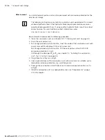
Observe the following information on versions with pressure relief valves.
▶
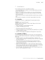
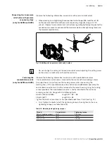
When screwing in and tightening the connection line to the port P
St
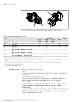
, hold the nut (1)
on the pressure relief valve with pressure sequencing stage (2) using an AF 24
wrench. Observe the manufacturer’s instructions regarding tightening torques for the
connection line used. Do not exceed the maximum permissible tightening torque on
the female thread (40 Nm).
1
P
St
2
Fig. 10: Holding nut on pressure relief valve in place
Do not change the setting of the pressure relief valve. Adjusting the setting screw
on the pressure relief valve will void the warranty.
Observe the following information on versions with counterbalance valves.
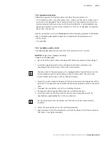
The counterbalance valve comes mounted to the motor with two tacking screws
(transport lock). Do not remove the tacking screws when connecting the
working lines. If the counterbalance valve and motor are delivered separately, the
counterbalance valve must first be fastened to the motor housing using the tacking
screws provided. The counterbalance valve is finally mounted to the motor by
screwing on the SAE flange with the following bolts:
6 bolts (1, 2, 3, 4, 5, 8)
Length B1 + B2 + B3
2 bolts (6, 7)
Length B3 + B4
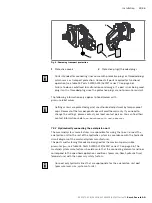
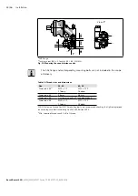
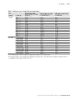
Tighten the bolts in two steps in the specified order from 1 to 8 (see Fig. 11).
▶
First, tighten the bolts to half the tightening torque, then tighten to the max.
tightening torque (see table Table 13).
Table 13: Mounting bolt tightening torques
Thread
Property class
Tightening torque
M6 x 1 (tacking screw)
10.9
15.5 Nm
M10 x 1.5
10.9
75 Nm
M12 x 1.75
10.9
130 Nm
Connecting line to pressure
relief valve with pressure
sequencing stage
(only for A2FM and A2FE)
Fastening the
counterbalance valve
(only for A2FM and A2FE)


