background image

 Operation

BOMAG

47

BMP 8500

4.11 Replacing, recharging the 

radio remote control power 
pack

i

Note

As standard the power pack is recharged in the 
machine through the spiral cable. A separate bat-
tery charger is available as an option. The re-
charging time is approx. 6 hours.

!

Danger

Operate the battery charger only in dry rooms 
at temperatures of min. 0 °C to max. 40 °C!

A charged power pack is a concentrated ener-
gy source! Do not store charged power packs 
in a tool box or similar, because metal parts 
may cause a short circuit. Short circuits may 
also be caused by keys etc. in a trouser pock-
et.

!

Caution

Change the power pack only when the sender 
is switched off.

Before connecting the battery charger make 
sure that the mains voltage is in accordance 
with the specifications mentioned on the bat-
tery charger.

Strictly follow the operating instructions for 
the battery charger.

i

Note

Ageing of the power pack reduces the discharging 
capacity and therefore the operating time of the 
sender.

The full discharging capacity is only reached after 
several charging cycles.

i

Note

As the charging of the power pack succeeds, the 
charging current drops, so that overcharging of the 
power pack is almost impossible. However, if the 
control is switched off for a couple of days (holi-
days, bad weather) you should also disconnect the 
charging unit from the mains supply or switch off 
the main battery switch.

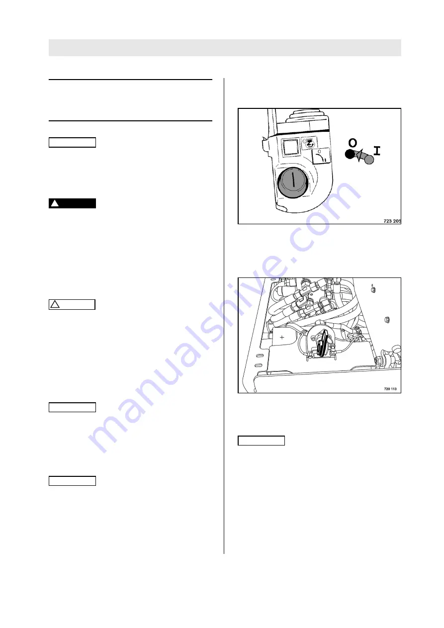
Charging the power pack in the ma-
chine

Fig. 69 

l

Switch off the transmitter (Fig. 69) with the ig-
nition key.

l

Plug the spiral cable into the transmitter

Fig. 70 

l

The main battery switch (Fig. 70) must be 
switched on.

i

Note

The power pack recharging time is approx. 6 
hours.

Summary of Contents for BMP 8500

Page 1: ...Operating instructions Maintenance instructions Original operating instructions Catalogue No 008 059 81 08 2011 BMP 8500 S N 101 720 11 1930 Multi purpose compactor BSS0134R...

Page 2: ......

Page 3: ...the right for technical modifications without prior notification These operating and maintenance instructions are also available in other languages Furthermore the spare parts catalogue is availa ble...

Page 4: ...3 Motor number Fig 3 i Note Supplement the above data together with the com missioning protocol During commissioning our organisation will in struct you in the operation and maintenance of the machine...

Page 5: ...the radio remote control in case of radio interferences 50 4 14 Switching ECO mode on and off 50 4 15 Entering the machine type code 51 4 16 Teaching the BOSS safety system transponder 52 4 17 Assemb...

Page 6: ...ines 86 5 26 Checking the injection pressure 86 5 27 Checking the fuel injection pump 87 5 28 Checking the fuel injection timing 87 5 29 Check clean replace the combustion air filter 89 5 30 Adjust th...

Page 7: ...BOMAG 7 BMP 8500 1 Technical Data...

Page 8: ...load CECE kg 775 1709 Travel characteristics Travel speed 1 forward reverse km h mph 1 3 0 8 Travel speed 2 forward reverse km h mph 2 5 1 6 Max gradability without with vibration soil dependent 55 45...

Page 9: ...PL c Reach of the safety field infront of behind the machine m ft 1 20 3 94 Safety field control Voltage V 8 30 Current consumption at 12 V A 1 5 Protection class IP 55 Safety field frequency kHz 125...

Page 10: ...t m ft approx 30 98 4 Current draw mA approx 10 Weight kg lbs approx 1 6 3 5 Receiver Receiver frequency range MHz 868 916 Current draw mA approx 10 Transmitter power pack Voltage V 3 6 Capacity Ah 1...

Page 11: ...conditions typical for this type of equipment and by application of harmo nized standards During operation these values may vary because of the existing operating conditions Noise value Sound pressure...

Page 12: ...Technical Data BOMAG 12 BMP 8500...

Page 13: ...BOMAG 13 BMP 8500 2 Safety regulations...

Page 14: ...l Earthwork in sewer and pipeline construction l Earthwork in railway and dam construction l Earthwork in sanitary landfill construction l Subbase and foundation work The place of the operator is beh...

Page 15: ...l equipment not sup plied by us The installation and or use of such products can impair the active and or passive driv ing safety The manufacturer expressly excludes any liability for damage resulting...

Page 16: ...control elements Do not take any loose objects with you or fasten them to the machine Starting For starting set all control levers to neutral posi tion Do not use any starting aids like start pilot or...

Page 17: ...from edges and embankments Checking the effect of vibration When compacting with vibration you must check the effect on nearby buildings and underground supply lines gas water sewage electric power if...

Page 18: ...layer is damaged down to the inlay e g chafing cuts cracks l the outer layer is brittle formation of cracks in the hose material l the hose shows deformations in pressurized and depressurized conditi...

Page 19: ...Repair work must only be performed by qualified and authorized persons Use our repair instruc tions for this work Exhaust gases are highly dangerous Always en sure an adequate supply of fresh air when...

Page 20: ...assume liability for changes and modifications not performed by us Information and safety stickers decals on the machine Keep safety stickers in good and legible condition see parts manual and comply...

Page 21: ...ion sticker Lifting point 6 Information sticker Diesel 7 Information sticker Battery disconnecting switch 8 Brief operating instructions 9 Instruction sticker Wear ear defenders 10 Information sticker...

Page 22: ...Safety regulations BOMAG 22 BMP 8500 Fig 8 Information sticker Bio Hydraulic Oil Fig 9 Information sticker Panolin 46 Optional equipment Optional equipment...

Page 23: ...BOMAG 23 BMP 8500 3 Indicators and Controls...

Page 24: ...Indicators and Controls BOMAG 24 BMP 8500 Fig 10...

Page 25: ...dio remote control 4 Main battery switch 5 Steering lever 6 Toggle switch vibration automatic manual 7 Toggle switch travel ranges 8 Toggle switch engine speed 9 Travel lever 10 Toggle switch for vibr...

Page 26: ...ights if the engine oil pressure is too low Check engine oil level repair the en gine if necessary b yellow Charge control lamp Lights if the battery is not being charged Check the V belt if necessary...

Page 27: ...stops Move the travel lever accordingly to free the machine from the obstruc tion j not used Fig 12 No 2 Fuse box F119 20A Fuse for starter motor F103 10A Fuse potential 15 F14 25A Fuse for engine so...

Page 28: ...AUTOMATIC po sition Vibration comes on automati cally when moving the travel lever after the toggle switch for vibration with high low am plitude has been actuated to any desired position Vibration sw...

Page 29: ...de Position mid dle vibration switched off Position rear low amplitude Fig 21 No 11 Emergency stop push button actuated transmitter and diesel engine will be switched off unlocked switches the transmi...

Page 30: ...24 No 14 Start button To start the engine in ignition switch position I Caution Perform the starting process for maximum 15 to 20 seconds without interruption and pause for about 1 minute between sta...

Page 31: ...BOMAG 31 BMP 8500 4 Operation...

Page 32: ...and mainte nance instructions l Park the machine on ground as level as possi ble l The operator must become acquainted with the size of the safety field Check l fuel tank and fuel lines for leaks l en...

Page 33: ...no longer in the safety field of the machine Caution The operator must become acquainted with the size of the safety field before he starts op eration If an operator is between 2 machines in both safe...

Page 34: ...hat the operator is fully acquainted with the function of the dif ferent control elements on the machine l Open the rear hood Fig 28 l Switch on the main battery switch Fig 28 l Strap the control to y...

Page 35: ...lt on the machine The control emits two short buzzer signals This in dicates that the control is ready for operation i Note If the buzzer does not sound there must be a fault in the control or the pow...

Page 36: ...erably reduce the ground adhesion of the machine on inclina tions and slopes Do not drive up and down inclinations exceed ing the maximum gradability of the machine see technical data Slowly return th...

Page 37: ...e will be switched to Eco mode low idle speed The engine will return to high idle as soon as either the steering or travel lever is actuated Fig 39 l Switch the toggle switch for travel speed rang es...

Page 38: ...To drive to the left Move the travel lever to the left Cleaning after use Caution Keep the cable remote control clean Rests of concrete clay or mortar may damage the bellows on travel levers and seali...

Page 39: ...avel levers 1 or 2 Fig 43 l Try to start the diesel engine The diesel engine must not start l Return the travel lever to neutral position rest position l Start the engine and actuate the control lever...

Page 40: ...rd or back The machine starts to move and the vibration switches on automatically The vibration will switch off when the machine comes to a halt Manual Fig 47 l Set the vibration switch Fig 47 to posi...

Page 41: ...en gine run for another few minutes for cooling Fig 50 l Turn the ignition switch Fig 50 to position 0 Fig 51 l Pull off the ignition key Fig 51 and store it in a safe place Fig 52 l Switch off and pu...

Page 42: ...repair the machine accordingly Fig 53 l Turn the ignition switch Fig 53 to position 0 Fig 54 l Pull off the ignition key Fig 54 and store it in a safe place l Fold the engine hood open Fig 55 l Keep t...

Page 43: ...r pack only when the sender is switched off Fig 58 l Turn the ignition switch to position 0 Fig 58 and pull it off Fig 59 l Insert the replacement power pack into the re ceptacle Fig 59 and let it cli...

Page 44: ...to po sition 0 Starting the engine i Note Before starting the engine both travel levers and the vibration control lever must be in rest position neutral The radio remote control is equipped with a re...

Page 45: ...down The warning buzzer starts to sound approx 1 minute before the shut down Drive the machine to a safe place as soon as pos sible so that it will not stop all of a sudden If necessary switch over t...

Page 46: ...he power pack of the remote control is to be re charged via the remote control cable the main battery switch Fig 67 must be switched on Cleaning after use Caution Keep the radio remote control clean R...

Page 47: ...e is in accordance with the specifications mentioned on the bat tery charger Strictly follow the operating instructions for the battery charger i Note Ageing of the power pack reduces the discharging...

Page 48: ...e power pack forward and lift it out of the housing Fig 72 Fig 73 l Push lock 1 Fig 73 on the mains unit of the battery charger forward and pull plug 2 up ward out of the mains unit Fig 74 l Plug the...

Page 49: ...ake sure that there are no persons within the danger zone Caution Rests of mortar or concrete may restrict the movement of the travel control levers Check from time to time with the sender switched of...

Page 50: ...range of the machine Fig 78 l Switch on the ignition Fig 78 and restart the machine Operation can be resumed 4 14 Switching ECO mode on and off Input of code numbers Caution The code can only be enter...

Page 51: ...g the machine type code Caution After replacing the machine control BLM the machine type code must be entered again The machine must not be operated with a wrong type settings as otherwise the correct...

Page 52: ...h off the main battery switch l replace defective components l switch on the main battery switch l plug the spiral cable into the remote control Fig 82 l Turn the tumbler switch for the cable remote c...

Page 53: ...ess than the gradability of the ma chine Make sure that persons are not endangered by the machine tipping or sliding off Always engage the articulation lock before loading lifting and transporting the...

Page 54: ...on of centre of gravity Fig 87 Fig 88 l Drive the machine onto the transport vehicle and lash it down by the two lashing eyes Fig 88 Danger Danger of accident The machine cannot be steered if the arti...

Page 55: ...BOMAG 55 BMP 8500 5 Maintenance...

Page 56: ...h inside zinc lining are not suitable to store fuel l When choosing the storage place for fuel make sure that spilled fuel will not harm the en vironment l Do not let the hose stir up the slurry at th...

Page 57: ...ing to other comparable specifications may be used If low sulphur fuel 0 05 is used you must only use engine oils of API classification CF CF 4 CG 4 CH 4 and CI 4 For operation of an engine with high...

Page 58: ...ithin the validity area of the EPA standard As an alter native to no 2 D you may also use diesel fuel no 2 D S500 or S15 with ambient temperatures be low 10 C the diesel fuel no 1 D S500 or S15 should...

Page 59: ...VLP according to DIN 51524 part 3 or hydraulic oils type HV ac cording to ISO 6743 3 The viscosity index VI should be at least 150 observe information of manufacturer Bio degradable hydraulic oil The...

Page 60: ...40 C BOMAG PN 009 920 06 20 l SAE 10W 30 15 C to 30 C SAE 15W 40 15 C to 40 C SAE 30 5 C to 30 C SAE 10 30 C to 5 C Fuel Diesel Winter diesel fuel down to 12 C approx 24 litres Coolant Mixture of wat...

Page 61: ...ine oil level twice every day Depending on the load the engine is subjected to the oil consumption will drop to the normal level after approx 100 to 250 operating hours Maintenance after 50 operating...

Page 62: ...X 5 12 Change engine oil and oil filter at least 1x per year see foot note X 5 13 Check tension replace the V belt X 5 14 Clean radiator cooling fins X 5 15 Change the oil in the vibrator shaft housin...

Page 63: ...tion X Running in instructions Oil change after 50 and 250 operating hours then every 250 operating hours When using fuels with a sul phur content higher than 0 5 the oil change intervals must be halv...

Page 64: ...Maintenance BOMAG 64 BMP 8500...

Page 65: ...il level is too low top up oil immediately l If the oil level is too high determine the cause and drain the oil off 5 7 Checking the hydraulic oil level Caution If during the daily inspection of the o...

Page 66: ...uel can cause malfunction or even damage of the engine l Fill in fuel through a funnel with screen l Close the tank again 5 9 Check the water separator i Note The service intervals for the water separ...

Page 67: ...sation tank only when the engine is cold Caution If during the daily inspection the coolant level is found to have dropped check all lines hos es and engine for leaks For quality of coolant refer to f...

Page 68: ...Every 10 operating hours BOMAG 68 BMP 8500...

Page 69: ...he engine oil fil ter Caution The oil change at 250 operating hours refers to the use of fuels with a sulphur content of less than 0 5 When using fuels with a sulphur content higher than 0 5 the oil c...

Page 70: ...irt Fig 97 l Slightly oil the rubber seal on the new filter car tridge Fig 97 l Turn the new filter cartridge on by hand until the seal contacts l Tighten the filter element for another half turn Fig...

Page 71: ...han 7 to 9 mm be tween the V belt pulleys retighten if neces sary Tensioning the V belt Fig 101 l Slacken the fastening screws 1 and 2 Fig 101 slightly l Press the generator in direction outward using...

Page 72: ...when cleaning i Note Dirt on fan blades and radiator reduce the cooling effect Dirt deposits in these areas are substantial ly supported by oil and fuel on these surfaces For this reason you should al...

Page 73: ...in for a while and spray it off with a strong wa ter jet l Run the engine warm for a while to avoid cor rosion 5 15 Change the oil in the vibra tor shaft housing Caution Change the oil at operating t...

Page 74: ...it adequately Fig 106 Fig 107 l Top up oil through the oil drain hole in the bot tom drum For quality and quantity of oil refer to the table of fuels and lubricants l Screw the drain and ventilation...

Page 75: ...of oil refer to the table of fuels and lubricants l Screw the drain and ventilation plugs back in 5 16 Checking the central screw of the drive hub Caution Check the tightening torque of the central s...

Page 76: ...Every 250 operating hours BOMAG 76 BMP 8500...

Page 77: ...nder the fuel tank drain plug Fig 112 l Unscrew the plug and drain off fuel l Once all fuel has run out screw the drain plug back in with a new seal ring l Fill the fuel tank with clean fuel 5 18 Chan...

Page 78: ...e fuel system Fig 115 l Open the bleeding screw on the fuel filter Fig 115 and crank the engine with the starter un til fuel runs out without air bubbles l Retighten the bleeding screw Fig 116 l Open...

Page 79: ...12 3 V 50 discharged l Recharge the battery immediately after an open circuit voltage of 12 25 V or less is reached Do not perform quick charging The open circuit voltage of the battery occurs ap pro...

Page 80: ...Every 500 operating hours BOMAG 80 BMP 8500 5 20 Check the rubber buffers Fig 118 l Check all rubber buffers Fig 118 for tight fit cracks and damage and replace immediately if damaged...

Page 81: ...the engine until both valves on cylinder 1 are overlapping l Perform the adjustment of the valve by follow ing the adjustment diagram 1 Fig 119 black mark Fig 120 l Check the gap between rocker arm an...

Page 82: ...safety field length 1 20 m is not permitted Fig 122 l Step behind the machine with the remote con trol and allow the machine to move towards you until it stops l Measure the distance between machine...

Page 83: ...ants When changing from mineral oil based hydrau lic oil to an ester based biologically degradable oil you should consult the lubrication oil serv ice of the oil manufacturer for details Environment C...

Page 84: ...ent Caution Always screw the radiator cap tightly back on second detent Always fill the engine cooling system with an anti freeze mixture corrosion protection Do not use more than 50 anti freeze Do no...

Page 85: ...on the engine l Drain the coolant completely off the engine block and collect it l Close the drain tap again Fig 129 l Fill in coolant until the level reaches the bottom edge of the radiator filler s...

Page 86: ...ourse of time Danger Fire hazard When working on the fuel system do not use open fire do not smoke and do not spill any fu el Do not inhale any fuel fumes Environment Catch running out fuel do not let...

Page 87: ...ery 3000 operating hours 5 27 Checking the fuel injection pump i Note This work must only be performed by authorized service personnel 5 28 Checking the fuel injection timing i Note This work must onl...

Page 88: ...Every 3000 operating hours BOMAG 88 BMP 8500...

Page 89: ...ective because of damage e g cracks and cause engine damage When working in dusty environments the filter service may become due considerably earlier This my be noticed by a drop in engine power and b...

Page 90: ...e engine and cause wear l Check the old filter element The old filter element can be of help to discover foreign particles on the sealing face which could lead to leaks A dust strip on the clean air s...

Page 91: ...nwards Dry cleaning of the filter cartridge Danger Eye injury Wear protective clothing goggles gloves Fig 139 i Note For cleaning purposes fit a tube to the compressed air gun Fig 139 the end of which...

Page 92: ...ric unified thread Fig 141 Strength classes for screws with untreated non lubricated surface Screw quality designations are stamped on the screw heads 8 8 8G 10 9 10K 12 9 12K l Drum extension drum 65...

Page 93: ...arts l After this test run remove the cylinder head covers and the lateral cover of the injection pump spray the rocker chambers and the spring chamber in the injection pump with a mixture of diesel f...

Page 94: ...As required BOMAG 94 BMP 8500...

Page 95: ...BOMAG 95 BMP 8500 6 Trouble shooting...

Page 96: ...e or insufficient mainte nance Whenever a fault occurs you should there fore thoroughly read these instruction on correct operation and maintenance If you cannot locate the cause of a fault or rectify...

Page 97: ...slow Clean the pole clamps tighten and cover them with acid free grease Especially in winter use of too viscous en gine oil Use an engine oil complying with the am bient temperatures Fuel supply too...

Page 98: ...r Remove any clogging from the cooling air duct Engine has too low oil pressure engine must be immediately shut down Leaks in the lubrication system oil level too low Check fittings on oil lines and l...

Page 99: ...Display off pull button out Switch defective replace Fuses F 54 F 67 F 103 defective Replace the fuses may be damaged by vibration Toggle switch cable radio S101 Check plug connections bridge switch f...

Page 100: ...n module A 70 indicates that the battery is empty if necessary re place the battery Inclination sensor Check the sensor signal input code 1405 Bridge connections 5 and 6 on the plug for the inclinatio...

Page 101: ...g loom Check whether plug X3 30 or X3 31 is loose Check for short circuit between X24 6 and 7 or CAN und CAN or 8 and 3 on the display module A 70 module BLM Replace the module Engine not running at m...

Page 102: ...nsmitter more than 30 m Move closer to the machine Toggle switch radio cable S101 Check the plug connection Bridge switch for testing Transmitter or receiver defective Replace transmitter or receiver...

Page 103: ...Emergency stop push button Switch operated Display off pull button out Switch defective replace Transmitter or receiver defective Replace transmitter or receiver Main wiring loom Replace the main wiri...

Page 104: ...ty field Transponder in transmitter has not been taught see chapter Safety equipment teaching the BOSS safety system transponder Safety antenna front rear defective or not plugged in Replace the anten...

Page 105: ...BMP 8500 6 6 Fault indicator Fig 142 Faults are displayed in the display module h Fig 142 in form of flashing fault codes If several faults occur at the same time these will be indicated by flashing...

Page 106: ...rminal on BLM Input code for diag nose 1030 Output is switched off function no longer possible Output valve travel ling forward Y 16 Too high current flow out of this output Out put was switched off E...

Page 107: ...unction no long er possible Output valve travel ling reverse Y 17 No or too low current flow out of this output Wire breakage in cur rent path Current path con nected to 12V X3 24 1040 1041 1042 1043...

Page 108: ...e Output brake valve Y 04 Short circuit current flow out of this output Output was switched off Short circuit to ground in the current path Lines rubbed through Valve defective X3 40 1062 Output is sw...

Page 109: ...e vibra tion high ampl Y 57 Too high current flow out of this output Out put was switched off Excessive current flow in current path probably because of a defective coil or a short circuit to ground X...

Page 110: ...of this output Wire breakage in cur rent path Current path con nected to 12V X3 19 1010 1011 1012 2013 Engine is shut down Output valve steer ing right Y 237 Although the output is switched off voltag...

Page 111: ...off all outputs on control are switched off Remote control emergen cy stop Emergency stop on remote control operated 2601 Engine stopped emergency stop relay in the control is switched off all outputs...

Page 112: ...o low Battery defective Battery discharged 0561 5020 Only warning horn sounds Input engine oil pressure B 06 Oil pressure switch delivers the signal no engine oil pres sure The oil pressure switch has...

Page 113: ...ctive coil or a short circuit to ground X3 10 5041 Output is switched off engine stops Output HW shut down solenoid Y 13 Short circuit current flow out of this output Output was switched off Short cir...

Page 114: ...13 No or too low current flow out of this output Wire breakage in current path Current path con nected to 12V X3 09 5050 5051 5052 5053 Output is switched off engine runs only with idle speed Output...

Page 115: ...path con nected to 12V X3 07 5060 5061 5062 5070 Output switched off engine cannot be started Output relay K 39 starter Too high current flow out of this output Output was switched off Excessive curr...

Page 116: ...8 Horn may sound continuously Output horn H 07 Although the output is switched off volt age is present Current path con nected to 12V X3 08 X3 36 5080 5081 5082 5090 Machine does not start Input incli...

Page 117: ...ault Possible cause Terminal on BLM Input code for diagnose Code Fault reaction Description of fault Possible cause 6001 Machine travels for 15min without activated BOSS safe ty system Attention Only...

Page 118: ...transponder Wire breakage in current path 6016 Reception quality safety field control Code Fault reaction Description of fault Possible cause Code Fault reaction Description of fault Possible cause T...

Page 119: ...ft Y 238 Current at output Display value output current in Amper 1022 Output valve steering left Y 238 Logic level of control 0000 Output not triggered 0001 Output triggered 1030 Output valve travelli...

Page 120: ...01 Output triggered Input code Description of display function Display values Input code Description of display function Display values 1305 Output valve vibration low amplitude Y 56 Voltage at output...

Page 121: ...101 12 V Operating mode wireless Input code Description of display function Display values 5010 Engine speed Display value 1 min 5020 Engine oil pressure B 06 Shows status of input engine oil pressur...

Page 122: ...play value output current in Amper 5062 Output relay K 11 potential changeover Logic level of control 0000 Output not triggered 0001 Output triggered 5070 Output relay K 39 starter Voltage at output D...

Page 123: ...ver shifted forward 0010 Travel lever not moved 0001 Travel lever shifted backward 2501 Actuation of steering joystick on remote control S 137 0100 Joystick actuated to the left 0010 Joystick not move...

Page 124: ...display function Display values 0660 Switches on function Set remote control type See adjustment instructions 0661 confirms the entered remote control type See adjustment instructions 0662 Preselect...

Page 125: ...es operating hour meter The minute digits of the operating hour me ter are displayed Input code Description of display function Display values 7010 Switches on function Set machine type See adjustment...

Page 126: ...Trouble shooting BOMAG 126 BMP 8500...

Page 127: ......

Page 128: ......

Reviews: