background image


68 

14.12.6.


MD3200M Monitoring & Playback 


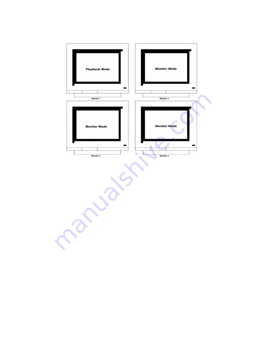
Monitor 1~4 are capable of searching several video/playback in single & divided sreen. Namely, several 

channels can be monitored and playback separately and simultaneously. But Playback can be monitored 

in 1 monitor among Monitor 1~4, and the rest 3 monitors for monitoring. 


Summary of Contents for BL-32960M

Page 1: ...DVR Installation User s Guide BL 1680A BL 32960M v 1 4...

Page 2: ...t This equipment generates uses and can radiate radio frequency energy and if not installed and used in accordance with the instruction manual may cause harmful interference to radio communications Op...

Page 3: ...llation 5 Product is made of metal Therefore you can hurt human beings if you throw it to them or hit on them When installing product be cautious to locate on safe places where children are unreachabl...

Page 4: ...box to edit a word 20 6 Setting remote controller 22 6 1 Setting ID of eDVR 22 6 2 Selecting eDVR 23 6 3 Operable range of remote controller 23 6 4 Loading the batteries into remote controller 23 7 e...

Page 5: ...9 2 1 Specifications 34 9 2 2 Connecting relay out 34 9 2 3 Configuring relay out as OSD menu 36 9 3 Connecting serial port 37 9 3 1 Configuring serial ports for Pan Tilt Zoom 37 9 3 2 Diagram of seri...

Page 6: ...13 3 Summery of Installation 55 Basic Structure 57 14 Monitoring 57 14 1 Basic Screen monitoring 57 14 2 Single full screen mode 57 14 3 Multi screen mode 57 14 4 Manual Recording 58 14 5 Auto Switch...

Page 7: ...Playback channel no 5 16 at 4 9 channel division 69 15 1 4 Zoon Playback screen 69 15 1 5 Various Playback functions 70 15 2 Search mode 71 15 3 Copy Backup Delete 72 15 3 1 Copy Image 72 15 3 2 Back...

Page 8: ...sion Change of video location 141 17 3 2 Change to Resolution 143 17 3 3 Change of Frame Rate 143 17 3 4 Moving Playback 144 17 3 5 Channel On Off 144 17 3 6 Sensor Indication 144 17 3 7 Relay Operati...

Page 9: ...3 4 Connectivity 165 18 3 5 COM Port 169 18 3 6 PTZ 170 18 3 7 Text 173 18 3 8 Audio 173 18 3 9 User 174 18 3 10 IP Filtering 176 18 3 11 Storage 177 18 3 12 Miscellaneous 178 18 3 13 System Log 178...

Page 10: ...rial Setup 191 19 3 Using PTZ 192 19 3 1 Serial Setup at COM port 192 19 3 2 Setup from Camera 193 19 3 3 Check PTZ operation 194 APPENDIX 195 1 HDD 196 1 1 Fundamental notions terms 196 1 2 Installat...

Page 11: ...optimize video quality and recording performance Also eDVR Series can extend the storage to maximum 8TB through IEEE 1394 eSATA and Network Storage For easy backup it is easy to apply through user PC...

Page 12: ...eSATA Network Storage Various Recording playback Independent file system for effective alarm data management Recording text data from ATM POS in relevant to video data 16 sensor input 4 alarm output...

Page 13: ...only DVD backup CD backup will be supported later For the details please contact to local distributor Note Extension through NVS04 IEEE 1394b will be supported later For the details please contact to...

Page 14: ...e 1EA 4 Remote Controller 1EA 5 RACK FIXING KIT 1SET 6 R HDD screw 8EA Note Attention for the system without HDD installed In case of system without HDD HDD only can only be installed in R HDD Removab...

Page 15: ...15 3 Description Function front 1 Power switch 2 Function buttons 3 LED 4 USB port 5 Remote controller receiver 6 CD DVD RW ROM 7 8 Built in Hard Disk Rack...

Page 16: ...00M BNC connector for video input MD3200M 12 Terminal block for sensor relay and serial input output 13 RS232 connector 14 VGA connector 15 IEEE1394 connector 16 eSATA connector 17 Network Storage con...

Page 17: ...ce 75O automatically Impedance is set as 75O basically If connecting a device to video output impedance will be Hi z status Please refer to 9 6 connecting Video In Output on page 12 3 Video Type NTSC...

Page 18: ...ded into Video Out 1 4 H1600L H3200M 1 2 H1600M and connect to Video Out 1 for the use of 1 monitor only 4 3 Connecting Audio 1 Connect auto signal to eDVR with using RCA cable 4 4 Supplying power 1 C...

Page 19: ...ng power eDVR starts booting automatically 2 In order to cut off power press the power switch on eDVR front during 4 seconds and enter admin password after appearing a pop window 3 For supplying again...

Page 20: ...the sub menu list To move to the setting page press button To exit the setting page press the EXIT button 3 Setting Page The selected sub menu is shown as a circle on the left side of the name and gra...

Page 21: ...shown using arrow buttons In case of spacing words press to move one space and enter the word To exit the Dialogue box press the arrow button 2 Available words range to use 1 2 3 4 5 6 7 8 9 0 A B C...

Page 22: ...button 3 Select Miscelleaneous from the sub menu list using the button and press button 4 Select Remote Control ID and press the 5 Select a value using the buttons and press the EXIT button 6 Press th...

Page 23: ...ng 2 seconds Note Because remote controller ID is sixteen eDVR will correspond until pressing ID button sixteen times 6 3 Operable range of remote controller 6 4 Loading the batteries into remote cont...

Page 24: ...24 7 eDVR configuration 7 1 Basic configuration 7 2 Advanced configuration...

Page 25: ...25 7 3 External storage Back up configuration 7 4 Internet Intranet configuration...

Page 26: ...rts automatically and images are displayed in basic 16ch split screen after the booting Note If user password is set a prompt for entering the password will appear Facotry default is reserved as not r...

Page 27: ...and press EXIT 8 2 2 Daylight Saving 1 Daylight Saving Time is only activated for Time Zone that uses Daylight Savings 2 Select Daylight Saving using the or button and press button 3 Select On Off us...

Page 28: ...r buttons and press 2 Select HH MM using the buttons and select the value using the button 3 Press the EXIT button when setting is finished 8 2 7 Apply Date Time Most setting values are applied automa...

Page 29: ...s MENU button and select Quick Setup when OSD menu is shown 2 Move to sub menu by pressing or button 3 Select Recording using the buttons and press 8 3 1 Configuration Status Displays the recording co...

Page 30: ...sing the button and press 2 Select a value using the button Press the EXIT button when it is finished 8 3 4 Quality When Recording Speed Quality is set as Custom values can be set normally 1 Select Qu...

Page 31: ...Wire gage should be AWG 20 26 Inserting removing wire To insert remove wirte in TERMINAL BLOCK use a screwdriver in the diagram to the right 9 1 Connecting and configuring sensor 9 1 1 Specification...

Page 32: ...S1 S16 with referring to the followings It shows to connect a dry contact Please refer to Note Wire Handling on page 27 When connecting a non dry contact type of sensor e g Open collector output pleas...

Page 33: ...ting all 16 sensors simultaneously which can be selected as Do not use Off Normal Open N O and Normal Close N C 1 Select a Global and set a type as Off N O or N C 2 Press Apply to save a configuration...

Page 34: ...9 2 1 Specifications In order to run relay output of eDVR normally the following conditions are required Output Ch 4Ch relay differential outptus Output type Dry Contact Spec Connecting type Connect t...

Page 35: ...35 Note Wire Handling on page 27...

Page 36: ...or or MD and its condition can be set differently according to schedule When using the Relay button Number button on the front panel or Control Center Lite D S W relay can be operated from remote site...

Page 37: ...not supported can still be controlled using the Transparent Protocol For a list of supported protocols refer to the list on the OSD Configuration menu The following figure shows how to connect PTZ cam...

Page 38: ...38 9 3 2 Diagram of serial ports 9 3 2 1 Diagram of COM1 RS232 9 3 2 2 Diagram of COM2 COM4 9 3 2 3 Diagram of COM3...

Page 39: ...s and available models at System Serial Setup in eDVR After completing serial setup configure base address or port for each channel at Camera menu tab When connecting PTZ devices to several cameras be...

Page 40: ...ice ATM POS Access Control The eDVR can record text data received from POS ATM through the COM RS232 serial port Connect to COM1 RS232 9Pin D Sub of eDVR and configure the Serial Setup sub menu under...

Page 41: ...ial setup COM1 at OSD menu 1 Set the System in OSD menu and move to Serial Setup menu 2 Select COM in Serial Setup set Devices as Text 3 Set Baud Rate Parity Stop bit with referring to manual of the c...

Page 42: ...1 Select the Alarm Source menu among OSD menus 2 Select the Text and set each value Note Before installing any external device consult with the local BLUNET distributor Some external devices may not b...

Page 43: ...tput Voltage Current Max 200mA per DC 5V Port Note The disk should be formatted with FAT32 type If properly connected the disk is recornized automatically as in the following pricutre To copy images t...

Page 44: ...tus and video impedance automatically For example when eDVR is connected by only video input the video impedance is set as 75O And when video in output is connected simultaneously the video impedance...

Page 45: ...R Before purchasing consult the local BLUNET s local distributor 10 2 Connecting IEEE1394 Device When using FireWire supported external HDD hard drive bays can be connected to 2 ports in the rear pane...

Page 46: ...ally run on start up make sure the HDD is properly installed 1 Press button marked at Select Disk 2 Select new added HDD indicated as F using button and press EXIT 3 Select Action using button and pre...

Page 47: ...same way as local access for controlling monitoring features 11 1 Connecting Ethernet 1 Turn off power switch of eDVR 2 Connect eDVR to hub with Ethernet cable 3 Turn on power switch of eDVR Note 1 Su...

Page 48: ...ns and press the button 4 Select IP Addr using the and press the button 5 Press EXIT button after entering IP address in the dialogue box 6 Select Net Mask using the buttons and press the button 7 Pre...

Page 49: ...Network and installed Contorl Center Lite on the PC 12 1 1 PC system requirements for running Control Center Lite Mininum Requirements Recommended Requirements CPU Intel Pentium4 3Ghz Hyper Thread Int...

Page 50: ...onents which wish to install and press Next button WESP SDK must be installed 4 Click the Install button after selecting a directory to be insatalled 12 3 Log In Enter User Name Password and press Ok...

Page 51: ...ol Click the icon on the desk top to run Control Center Lite Configuration Tool 12 5 Monitor Max 5 users could be connected simultaneously in one unit of eDVR Click the icon on the desk top to run Con...

Page 52: ...52 12 6 Playback Max 2 user could be connected for playback in one unit of eDVR Click the icon on the desk top to run Control Center Lite Playback...

Page 53: ...nd twinkle as many as image played at playback mode Also twinkle as many as image delivered per second when it connects to Control Center Lite D Playback 2 Remote controller receiver 3 Power Switch It...

Page 54: ...itor REC Function to start stop recording by user Start Stop user recording according to set in advance 6 Channel Select button Select video channel when monitoring playback Below LED on each channel...

Page 55: ...0M 5 Video Output 4 Video output 1 VGA Output MD1600H MD3200M 2 Video output 1 VGA Output MD1600M 6 Serial DIO port Sensor In 16 Sensor input terminal block Relay Out 4 Relay output terminal block COM...

Page 56: ...Ethernet connection for remote connection Audio connection Power connection Operation Note Extension through NVS04 IEEE 1394b will be supported later For the details please contact to local distribut...

Page 57: ...ore the following functions explains base on all Monitor 1 4 14 1 Basic Screen monitoring It turns on automatically when eDVR powered on It boots with LED on After booting 16 channel screens are displ...

Page 58: ...SEQ button 1 sec longer Attention System stardard mode is capable to use when channel division is more than the number camera connected Namely single at 2 or more cameras 4 division modes at more than...

Page 59: ...y division mode by the press SEQ button Press SEQ button once more to leave from Auto Switch mode 14 5 2 User Sequence mode Press SEQ button longer than 1 sec User Sequence is to set User Sequence Con...

Page 60: ...nnel 1 16 and Monitor 2 4 sets channel 17 32 Channel area is divided by each Monitor 14 6 Alarm mode It can be set to Pop up automatically relevant screen when alarming Set pop up period can be set in...

Page 61: ...e Live screen Live screen can pause like PlayBack Press PAUSE to pause live screen and press to return live screen 14 9 PTZ Control Connect PTZ controller to eDVR and set relevant protocol from Serial...

Page 62: ...ime monitoring mode Control camera location using Pan Tilt and Zoom Focus menu Press SELECT button and select Channel Press MENU then select Save Preset from OSD Press relevant Number button to set in...

Page 63: ...is displayed on when press RELAY button once more Rress relevant Relay button to Relay Off 14 11 Screen Lock control The function to prevent unauthorized user operating the menu at will Set User Passw...

Page 64: ...el 1 Also Monitor 3 for Sequence mode and Monitor 4 is capable of monitoring Alarm Pop up images Every Monitor 1 4 can be set in following conditions separately Monitor 1 Monitor 2 Monitor 3 Monitor 4...

Page 65: ...imultaneously But Playback can be monitored in 1 monitor among Monitor 1 4 and the rest 3 monitors for monitoring 14 12 3 MD1600M Monitoring Monitor 1 is for multichannel videos Monitor 2 is use for f...

Page 66: ...tor Alarm Pop up Monitor Multi Monitor 14 12 4 MD1600M Monitoring Playback Monitor 1 2 can search playback every images in Single or multi divisions Namely Monitoring and Playback is possible simultan...

Page 67: ...4 can be set in following conditions separately Monitor 1 Monitor 2 Monitor 3 Monitor 4 Multi Monitor Single Monitor Sequence Monitor Alarm Pop up Monitor Single Monitor Sequence Monitor Alarm Pop up...

Page 68: ...e capable of searching several video playback in single divided sreen Namely several channels can be monitored and playback separately and simultaneously But Playback can be monitored in 1 monitor amo...

Page 69: ...ack screen mode Pressing MULTI button every time it is changed 4 9 16 channel division Channel 1 4 images is playback in 4 channel division Select channel number to playback single channel playback mo...

Page 70: ...k FFW Change Playback speed at every button pressing x1 x2 x4 x8 x16 x32 x64 REW Reverse playback speed at every button pressing x1 x2 x4 x8 x16 x32 x64 If press REW button at Monitor mode it will rev...

Page 71: ...ENTER to move to the relevant time Order of Button Input Press SEARCH at Playback mode Input Date Time or select relevant Log from Log Browser Press button Playback searched image Press EXIT to exit f...

Page 72: ...ded images Press SELECT and MENU in order and Playback mode 15 3 1 Copy Image Use USB Memory Stick etc to copy selected channel images in some part Time Slect the range of Copy Range of image can set...

Page 73: ...Select Disk Select the disk to use backup device Note Uncompleted backup file 100 can not be played normally in PC Note It does not support USB device as backup It supports CD R DVD R and over CD R M...

Page 74: ...lete specific rage of data in present HDD recorded Delected data is limited to present HDD used and it does not affect to backup disk The range of delete data is from oldest data to the data that the...

Page 75: ...rding briefly Refer to each list as follow for the recording in detail 0 HW KRG RI 5 HFRU GL QJ 6 HW XS 0 H W K R G R I 5 H F R U G L Q J 6 H W X S 0 H W K R G R I 5 H F R U G L Q J 6 H W X S Type of...

Page 76: ...Recording Alarm Recording On Off List of Setup by Time Full Time Weekday Day Weekday Night Weekend Day Weekend Night Alarm Recording It can setup additional recording by Event at the setup condion of...

Page 77: ...to the local is very important to protect Recording data in a unit Factory set of Time is UTC 00 00 Dublin 16 1 1 1 Time Setup Press MENU at the front of eDVR Shift to Quick Setup menu Shift to Date T...

Page 78: ...d to Time zone set menu Namely it is activated when selected summer time zone is set from Tim Zone set menu Summer Time Zone is programmed to apply the time zone from existing MS Windows At these stag...

Page 79: ...ss Apply Date Time button to display the following window Note Except Date Time setup other setup is saved when the menu is closed but Date Time setup does not support auto saving because it can affec...

Page 80: ...Both NTSC PAL camera can not be used together to the system For example 1CH 5CH for NTSC camera and 6CH 8CH for PAL camera is not allowed Also after the change camera from the one of NTSC to PAL reboo...

Page 81: ...atus It can On Off the status of Camera Press On Off using or button after pressing ENTER button To raise frame rate while recording or network monitoring turn off the unusing channels Type Type is th...

Page 82: ...d setup and available camera list that support PTZ PTZ Port The menu is to set connected camera that support PTZ Pen Tilt Zoom After press ENTER use or button to set PTZ port connected to the relevant...

Page 83: ...ts recording condition to Quick Setup it is indicated to Macro Setup and Custom Setup when any set has changed from recording menu Note It is shown to Macro Setup in case of set Schedule Recording to...

Page 84: ...F Half D1 Full D1 It is possible to change when resolution setup is set to Custom at Recording Speed Quality Audio Recording It sets Audio recording In case of Audion recording set to On Audio Synch w...

Page 85: ...n of window At this time press Help button until Event appears After this window of normal recording channel is indicated to 16 1 4 Normal Schedule Recording This menu makes to set recording by channe...

Page 86: ...d sets whether Special Time Recrding Event Recording sets or not 2 What Alarm Recording Off is set Alarm Rec menu is not available To set Alarm Rec menu Alarm Recording of Recording menu should be set...

Page 87: ...Time Schedule It sets recording condition based on every time schedule Time period can be set 4 districted areas Full Time Weekday Day Weekday Night Weekend Day Weekend Night Day Night Weekday Weekend...

Page 88: ...zoon can be set to Weekend time zone Day Start End Set Day time zone using Up Down button The unset zoon can be set to Night time zone Recording Speed Quality There are all 5 setup conditions No Rec...

Page 89: ...Recording This menu is to differenciate recording conditions by setup of specific time zone Namely if it sets to day time in workday it can record according to 2 type setup condition Specific time set...

Page 90: ...ion It can set all cameras connected in sample recording conditions using Global menu 1 Set all cameras in same recording setup with Global menu 2 Press Enter at Full Time and set recording below 3 Se...

Page 91: ...HDD size it can set needed time for recording through schedule setup more effectively At Schedule recording setup it can set recording divided into schedule of Weekday Day Weekday night Weekend Day We...

Page 92: ...eekend Night means Saturday to Sunday 18 00PM 09 00AM 4 The above Time Schedule setup influences to recording setup by schedule of Schedule Recording setup menu Schedule Recording Setup To setup recor...

Page 93: ...record but monitoring is available 3 Select Special Time Recording Same as above 4 Select Alarm Recording Off 5 Press Apply If press Apply at Schedule Rec Global Weekday Day the same condition of Wee...

Page 94: ...now it records Weekday Night only and set to do not record Weebday Day or Weekend Day Night The condition of the above setup is applied to all cameras Every camera connected can also be set to record...

Page 95: ...re 3 Press Enter to Apply and move to the next camera to set 4 Cam 1 is set to full time recording 5 In case of other camera it can set full time recording like the setup of Cam 1 Other Camera Setup O...

Page 96: ...96 1 Move to Weekday Day to setup recording Cam 2 for Weekday Day 2 It can set recording wanted As above picture it set to record in Custom Speed 15 ips Quality Q5...

Page 97: ...cord for Weekday Day 16 1 5 Alarm Recording Setup This menu can set up Alarm Recording Alarm recording can work in recording by Sensor recording by Motion Detection and recording by Text To do Alarm r...

Page 98: ...Normal Close N C Global It set all sensors same together After select among Off N O N C and press Apply to activate Configuration It can set 16 sensors S1 S16 separately 16 1 5 1 2 Motion Detection Se...

Page 99: ...MD Area It can set all areas with selection of Set All and clear the selection through Clear All Note To set Global press Apply Other will be not applied 16 1 5 1 2 1 Motion Detection Setup by Channe...

Page 100: ...100 Custom Area It sets MD zone by user NTSC 22x15 PAL 22x18 First default value is set to Select All If Custom Area pressed Window for MD zone setup is opened...

Page 101: ...r setup is displayed Selected MD zone is in grey color To select MD zone use direction key for the wanted zone and press ENTER to apply After selection press EXIT to return previous menu 16 1 5 1 3 Te...

Page 102: ...meter to analyze how the one of data is constructed from the text data that is input continuously Namely all data has the first and the end Header indicates the information that already inserts to inf...

Page 103: ...requires only 1 shorter than other ATM users It is to decide the last line of the one data register as final complete data to save after an hour s consideration of register later because eDVR can not...

Page 104: ...channel for the details 16 1 5 3 Setup by Channel Alarm Source All Through Alarm Source 4 Sensors and 1 MD Text input is selectable Selection of Sensor is set by pressing relevant number button Selec...

Page 105: ...Recording it records Pre Alarm section in speed ips of a set Schedule Rec 2 When Post Alarm is set to Latched it maintains user recording continuously till the stop pressing REC button by user Alarm...

Page 106: ...ch channel and is set up MD On Note Cam 1 Select MD On Sensor 1 Cam 2 Select MD On Sensor 2 Cam 3 Select MD On Sensor 3 As above set alarm matching with each channel 4 As above picture set recording w...

Page 107: ...m Recording setup set MD Sensor For the detail of MD Sensor setup refer to 5 1 5 1 Alarm Source Setup Now it is alarm recording when MD Sensor alarm occurs 16 1 5 4 2 Alarm Recording Setup by Camera S...

Page 108: ...rding by schedule Set to ON OFF Alarm recording by Camera schedule 1 As above picture shows the Cam 1 is alarm record in day time during week 2 Select Weekday Day from Schedule Rec Cam 1 menu 3 Select...

Page 109: ...hedule Recording setup to operate alarm recording 16 1 6 Manual Recording Setup Manual Rec This menu is to setup recording condition when user press REC button at front of system If manual recording s...

Page 110: ...Rec Low Standard High Custom Setup condition except Custom will synchronize Speed ips and Quality automatically Speed ips and Quality can be set each separately Pre Alarm sec It means the time of reco...

Page 111: ...s can be divided into Event alarm action System alarm action Event Alarm action It means Relay E mail Buzzer Pop up OSD display PTZ preset operates by Motion Detection Sensor input Text input of event...

Page 112: ...mail Video Loss and Text can be set On Off Selection of Sensor MD is done by pressing relevant number button Note 1 ANY Press button Special Time It selects whether it apply specific time period that...

Page 113: ...f Buzzer or not E mail Addr Input E mail address to inform Alarm Sender Addr Input Sender address in the typr of who where Mail Duration min E mail notification is to send message in terms of Mail Dur...

Page 114: ...p It is to set ON OFF of Alarm for the notification of system faulty HDD Fail Alarm action is operated when HDD disconneced or abnormal action HDD Almost Full It operates alarm action when connected H...

Page 115: ...Warning Message When setup this menu it display warning message through pop up Warning Message remains On always Beep When set this menu it sounds Beep Send E Mail When this menu is sest it sends emai...

Page 116: ...icker OSD menu When it is On it soften Menu and Text on screen and no trembling But when it is Off the letter will be cleared and trembles Set On Off based on the condition of the user s monitor Note...

Page 117: ...ll mode 5 Full mode 8 9 divisions 9 10 11 12 13 14 15 16 16 4 System Setup 16 4 1 Audio Setup eDVR supports 4channel Audio recording But it operates with any channel when video playback Recording It s...

Page 118: ...ay Other unassigned time is for the Weekend Day Start End Using Up Down button sets Day time period Other time is applicable to the Night time 16 4 3 Special Time It can set another specific time zone...

Page 119: ...can set Exception Days It used for the setup of irregular exceptional time max 30 time zones Start Date Time Set Starting time Duration Set an interval of Exceptional time Profile Set the value of exc...

Page 120: ...1 Local Password User Password It is only capable of monitoring and playback only with user registery Default set is 1111 Admin Password Authorized administrator can control every function Default se...

Page 121: ...dmin cannot be changed Password of admin is set and has all rights and unchangeable User ID setup Max 10 user s ID can be set To register the user change Use s value to Y and input ID password Basic v...

Page 122: ...tomatically Backup Reminder This menu is to inform backup time by everyday every week every month Day Date Time It applies the value of setup differently according to value of Backup Reminder Block Pl...

Page 123: ...r LAN based connection It sets to xDSL when eDVR is connected to xDSL line of PPPoE method But it sets to Ethernet if it is not PPPoE method even if it is xDSL line DHCP DHCP Dynamic Host Configuratio...

Page 124: ...via HUB in small IP Address NetMask and Gateway Address DNS Port Bandwidth limit It sets IP address Network Mask Broadcast address Gateway DNS address and Port Bandwidth limit 16 4 6 2 xDSL When eDVR...

Page 125: ...To register Static IP to WRS please refer the following to set WRS Interval For continuous registery register inverval should be set to WRS Interval According to set value of static IP address it rene...

Page 126: ...e an entry Group ID Group ID is to set group name that eDVR registered It recommends uneasy Group name to avoid same Group name registered Status It indicates the status of eDVR registry 16 4 6 4 NTP...

Page 127: ...bles when NTP Mode is set to Client It sests whether NTP server is in Local Network or Internet Public NTP Local Server IP It enables when NTP Server Loc is set to Local and set Server IP Input IP of...

Page 128: ...connected Interface This menu is to set which interface can use among RS485 from RS485 menu COM1 COM3 is fixed to RS232 and COM2 COM4 is fixed to RS485 Baud rate Parity Stop bit Data bit In put suita...

Page 129: ...time of the recorded file Disk Capacity It shows total HDD capacity installed Used Space It shows HDD capacity recordable HDD Temp It shows HDD temperature installed HDD SMART It indicated HDD status...

Page 130: ...up and contril via 1 remote controller Set to Off if it is not used How to register Remote Controller Face Remote controller toward eDVR Press ID button on controller when eDVR is responding If ID of...

Page 131: ...ing Policy Recording Prior Networking Prior can be set If it set to Networking Prior besides basic recording resolution it can monitor with low resolution or QCIF resolution in according to condition...

Page 132: ...d to set system to initial factory setup Press Reset Values button to set factory setup mode 16 5 Disk Manager Utility It explains adding or formatting internal external Hard disk eDVR supports variou...

Page 133: ...ividing 1 HDD to Recording part and Alarm Recording part Remove Remove present HDD used logically Later it is possible to use it through Add used without formatting Confirm Removed Complete removal fr...

Page 134: ...se After upgrading DVR HDD that recorded in previous version is indicated to V in Disk Manager Select HDD in Select Disk Press Apply after selection of Add Used at Action Press OK at NOTICE Disk reuse...

Page 135: ...rint Settings txt Function to save Set value for printing into USB device in Text file Saved data file can be opend through Text editor like Notepad to print and check set value saved List of setup da...

Page 136: ...136 Save Settings Save present set value to USB device...

Page 137: ...ded into Login page and Monitor to do monitoring real time images Playback to replay reocorded images 17 1 LOGIN After input IP address that set to system then WebViewer Login page will be connected I...

Page 138: ...ID including administrator general user For the security change ID Password of admistrator For the unused user s account it cancels the check of Use part This is the changed ID Passwork at Control Ce...

Page 139: ...eck CH 1 and uncheck the rest channel and function 17 2 Usable Browser WebViewer is optimized to Windows Internet Explorer 6 0 or higher in PC for smooth use Webviewer Installer Login page provides ma...

Page 140: ...exe file downloaded it can use WebViewer function normally Save ID Select Save ID at check box it is to connect same User ID at next connection automatically It is applied to a PC that Save ID is act...

Page 141: ...nction according to user s authorization Study introduction of each Monitor part and functions of the page 17 3 1 Screen division Change of video location When access to first Monitor page it is displ...

Page 142: ...142 Double click on one of the playback screen to convert in 1 channel mode After conversion to 1channel mode double click on screen to return to previous division channels...

Page 143: ...is applied to all channels Note In case of MPEG product frame rate change and reolution change menu is not shown characterically Note When resolution changes video size is not changed The change of vi...

Page 144: ...of page 17 3 5 Channel On Off It is On Off button for the Channel located to left in page Click the channel wanted to On or Off And Default is On Above picture refer to Off channel 1 In case of Chann...

Page 145: ...isabled sensor button refers to do not support and relate to this unit 17 3 7 Relay Operation It can On or Off Relay of the unit Click the number button to activate Ralay On then the incon changes fro...

Page 146: ...nd it is changed from the Blue to Red when click the button for the use Mic Note Unactivated Relay button refers to do not support and relate to this unit 17 3 9 Event data It shows real time event da...

Page 147: ...uring Quick Recording recording time is indicated on video During video recording if click Quick Recording button to stop recording and open the dialogue box to store recorded files At this time user...

Page 148: ...iddle to activate Pan Tilt faster Zoom Focus Control Move mouse to the edge of left right to see slide bar for Zoom Focus The unit Area Zoom In available has Zoom Zero operating button It can Zoom In...

Page 149: ...e press right mouse button on the image for menu pop up then select Normal PTZ Mode to convert normal PTZ mode Note Refer to PTZ Setup list for PTZ camera list and PTZ setup Conntact to local supplier...

Page 150: ...ing by click Close at top right on screen then it comes to black screen To reconnect the channel disconnected it can reconnect relevant channel using Channel On Off menu 17 4 Playback This page is to...

Page 151: ...image or save to Bmp file 17 4 1 Video Division Changing Channel Playback supports 1 4 9 and 16 divisional screens It can select division using menu on tip of page as above picture 32ch DVR can call...

Page 152: ...nding to the selected channel and click Save button Save Iamge dialog box appears then it can input message or select channel name date event data Press OK to open dialog box for the saving location t...

Page 153: ...file format to backup In case of backup in rec file it can play through Control Center Playback program or Miniplayer And XVID codec is needed in PC playing in case of avi file back up Re4 backup can...

Page 154: ...channel recording time press Start button for the window that shows the backup processing status and processing backup When select avi file format File Split Size item disappears and replaced to Fram...

Page 155: ...time selected When click Go To button it indicates for 24hours from the time selected at left bottom As above picture it is possible to change the time zone with 24h button 17 4 9 Functional function...

Page 156: ...ick the button it can select play area 10min 30min 1hour 3hour 6hour 12hour 24hour It can select DirectX use or not If check DirectX mode it can play image into Direct Draw based on graphic card and p...

Page 157: ...tures 18 1 Log in Configuration Tool 1 Click icon to run Control Center Lite D Configuration Tool 2 Program Log in Click on OK button after inputting ID and Password When login becomes accomplished no...

Page 158: ...The list is periodically synchronized with My Units of Control Center Lite And when user press the Refresh button in lower part all the information will be renewed rightly The details which user can...

Page 159: ...out pressing Apply button dialogue box will appear to ask user whether new configuration will be applied 18 3 Setting DVR 18 3 1 System Setting System Info It displays basic information of i Rec Thing...

Page 160: ...is equivalent to the products Export Window for saving setting information will appear when cliking Export button Save setting information as file format Import Click Import to pop up Import Wizard wi...

Page 161: ...1 Check whether Model type of import and export is same and belongs to same category If they are same model type Import will be promptly started Enter Admin Password and press OK button to start Impor...

Page 162: ...on will be activated Reboot It is for rebooting DVR Factory Default It is for changing configuration into factory default value Z Note The information such as date time network setting and image type...

Page 163: ...each channel 18 3 2 2 Channel Information Enable Sets to use channel Channel Name Inputs channel name Camera Type Selects video type NTSC PAL Black White In case image is black and white 18 3 2 3 Imag...

Page 164: ...3 3 2 NTP Setup NTP Network Time Protocol is the function to sync the time with device which can be standard on the network Mode Select Server Client Both At Server mode DVR supply the time by itself...

Page 165: ...3 4 Connectivity 18 3 4 1 When using Ethernet Select Use DHCP If user uses dynamic IP address Input IP address subnet mask gateway and DNS server if user uses static IP address Note Please ask network...

Page 166: ...pes such as ADSL HDSL VDSL it can be used by PPPoE protocol 2 Set WRS when using xDSL type except using static IP address 3 Can not connect network by using ethernet xDSL 4 User ID and password will b...

Page 167: ...al Sets time interval when dynamic IP address is registered in WRS If IP address is changed frequently user had better set interval 1minute 1minute 1hour 3hour 6hour 12hour 24hour Server Address IP ad...

Page 168: ...such as firewall Idle Time User can set idle time User can wait for reconnection during idle time if connection is closed because of network problem If waiting time exceeds idle time connection it wil...

Page 169: ...PTZ in lower part of page If user wants to go to the PTZ set up page directly just click Go button TP Select it when user wants serial port to support Transeparent Protocol Transeparent Protocol can b...

Page 170: ...Enable Select it when user wants channel to be linked to PTZ Port Dependency Select the serial port which is linked to PTZ Address Set up Base Address of PTZ device User should input setting figure of...

Page 171: ...reset position will be deleted if user selects preset and click on clear button Note 1 PTZ adjustment can be done in pop up menu 2 User can control Pan Tilt only when user place mouse cursor inside an...

Page 172: ...vides various additional functions including basic functions such as Pan Tilt Zoom Dialogue box for setting max 16 auxiliary functions will appear if user clicks Auxiliary button Select Auxiliary afte...

Page 173: ...ext Set Recording menu to On and set Sync channel to the wanted value If connectable devuce is Star Finger 007 set the relevant device only And et other products to Manual and set all inferior menus 1...

Page 174: ...3 9 User 18 3 9 1 User Accounts There are two kinds of user one is administrator the other is common user The administrator has especially authority relating to changing setting of i Rec including al...

Page 175: ...User Password It is only capable of monitoring and playback only with user registery 18 3 9 2 User Authority User can set user s authority according to Microphone PTZ relay out HDD channel viewing Re...

Page 176: ...can give access authority of i Rec by using IP filtering It is allowed to access If IP address is registered Allow and it is not allowed to access if IP address is registered Deny Total ten IP can be...

Page 177: ...al size free size of HDD Auto Deletion When no space in HDD delete recorded data automatically Disk Full Alarm It shows the message checked of HDD capacity Block Playback This is menu to show limitedl...

Page 178: ...178 18 3 12 Miscellaneous If this is On it records video image which is not input 18 3 13 System Log It is used to view System Log...

Page 179: ...d end point of weekday the remaining day is automatically included in weekend Day time Set start point and end point of day the remaining hour is automatically included in night 18 3 14 2 Setting Spec...

Page 180: ...15 MD Set Motion Detection according to each channel User can also set sensitivity of MD User can not use MD if user sets sensitivity None Highest is most sensitive level None Lowest Low Standard High...

Page 181: ...181 18 3 16 Input Set sensor type user wants NC Normal Close NO Normal Open Off 18 3 17 Relay...

Page 182: ...ot want relay out to operate Relay Post Time Decides relay post time after events 1 3600 second Note 1 User can set time zone in Time Schedule page 2 Special time can be set maximum 4 Set up is done i...

Page 183: ...when malfunction of FAN connected to eDVR Password Fail It operates Alarm when wrong User or Admin password input WRS Reg Fail It operates Alarm when disconnection of WRS Alarm Method It is to set ON...

Page 184: ...other recording way of Special Time and set whether to use designated recording way in Alarm Recording group when alarm is occurred Alarm Recording ON OFF Set resolution and recording speed by using...

Page 185: ...hen set On it deals text input of relevant channe as Alarm Event and is saved Alarm Source Through Alarm Source 4 Sensors and 1 MD Text input is selectable Selection of MD Text can be On Off Select Pr...

Page 186: ...d and it records based on user recording setup Recording Speed Quality There are all 5 conditional setup No Rec Low Standard High Custom Except Custom Setup condition will synchronize Speed ips and Qu...

Page 187: ...devices Text menu RS232 menu of Serial Setup Alarm Rec menu Recording menu 19 1 1 Setup in Text Set Recording Monitoring menu to all On and set Sync channel to the wanted value If connectable devuce...

Page 188: ...188 19 1 2 Setup in RS232 menu of Serial Setup Set connectable device in COM1 of Serial Setup menu and also set Baud Rate Parity Stop Data with relevant value...

Page 189: ...189 19 1 3 Setup in Alarm Rec If there is video channel want to record with Text sync set Text Event from Off to On...

Page 190: ...differ the step of showing video data Default value at Monitoring shows channel number only And whenever pressing Help it changes to channel name text sign stage event status sign HDD status sign In o...

Page 191: ...menu of Serial Setup Set connectable device in RS232 in Serial Setup menu to Keyboard Also set Baud Rate Parity Stop Data with relevant value 19 2 2 Setup in PTZ menu of Serial Setup Set communication...

Page 192: ...l Setup menu and press Enter 8 Using key selects COM Port that PTZ connected Select COM2 RS485 and press Enter key 9 Press Enter key to select Device and select connected PTZ Using jey select WGI SPD1...

Page 193: ...and press Enter PTZ Home PTZ Idle Time The menus is to set the camera that support PTZ Pen Tilt Zoom When PTZ control move to preset assigned while PTZ Idle Time 3 Move to PTZ Idle Time and press Ente...

Page 194: ...BLUNET SPD1800 BLUNET SPD2600 Bosch autodome PELCO P PELCO D Sony EVI D3x VT VPT 4x AD speeddome Sungjin SJ3728R1 Marit lilin fastdome Canon VC C4 Honeywell scandome2 BOSCH TC8560X 4 Panasonic WV CS85...

Page 195: ...195 APPENDIX APPENDIX APPENDIX...

Page 196: ...d HDDs are recognized as one virtual disk and eDVR supports upto 8TB Note Log Partition To store the information of recorded data Normal Partition To store the data as normal recording schedule Backup...

Page 197: ...197...

Page 198: ...ed by the order of recognition 3 HDD Managing Command Add Add a HDD for recording In case of adding a disk Alarm Partition menu is activated as an available status Alarm Partition means that one HDD d...

Page 199: ...product and warrantee Installation of internal HDD In case of installation adding exchanging HDD please refer to following procedures 1 Disconnect the power to eDVR 2 Lossen a screw foxed on case 8pc...

Page 200: ...Unlock it using HDD RACK Key 5 Take out the bracket with the lift of handle 90 degrees at front 6 Disassemble cables connecte to Board and arrange them to outer case so as to secure the space for HDD...

Page 201: ...201...

Page 202: ...202 7 Push in bracket that HDD installed under HDD RACK It is easy to install if it push in leaning to the left...

Page 203: ...203 8 Insert a hand to the bottom space the as below of HDD RACK to adjust location set 9 Insert a hand to the bottom and lift up HDD bracket to drive a screw...

Page 204: ...isconnected at 10 6 to a board 11 Connect cable between HDD and Int A B SATA connector Int B SATA Connector Int A SATA Connector Rack B SATA Connector Rack A SATA Connector 12 Connect power cable to H...

Page 205: ...205 13 Install HDD RACK 14 Clise the case and drive a screw...

Page 206: ...not guarantee the warranty Installation and extension of internal HDD RACK HDD In case of installation adding or exchange HDD follow the procedure as followings 1 Cut off the power to eDVR 2 Release t...

Page 207: ...207 Note When assemble HDD the base of HDD should be HDD below 5 After insertion of BRAKET that HDD installed to RACK take the handle down to fix 6 Rock HDD RACK using KEY to complete installation...

Page 208: ...ect Action as Add configure a size of alarm partition and press Apply button Then F is changed to R 4 Press the EXIT button to shut down Disk Manager If recording schedule is set eDVR will start recor...

Page 209: ...d by the MD1600H Before purchasing consult the local BLUNET distributor 2 External storage should use external power 3 For connection and setup of IEEE1394 eSATA NVS04 please refer to the manual of re...

Page 210: ...ger 2 Select a second HDD of F Ext Press the Apply button after selecting action as Add Then F is changed to R Note If connecting the device that is used in eDVR type will be indicated as V 3 Select a...

Page 211: ...efer to the manual of related device 1 When external HDD RAID is connected to IEEE1394 port Disk Manager runs automatically If not run it manually in Menu Utility Disk Manager 2 Select a second HDD of...

Page 212: ...iting a disk comes from physical error or occuring a bad sector at the beginning of a disk it is decided as a disk error In case of being other disk inside eDVR or able to storage a data it is recorde...

Page 213: ...trol Center Lite D or MiniPlayer 3 Backup data is made as re4 file and recognized as CD R 700MB DVD R 4G per each file 4 Support CD R backup and should be over CD R 700MB DVD R 4G media 5 In course of...

Page 214: ...in R HDD Removable Hard disk rack For the internal installation of HDD additionally For the details please contact to local distributor Note It supports only DVD backup CD backup will be supported la...

Page 215: ...e Management Program Acrobat Reader Version 7 0 Preparation To read manual of CD ROM disc Adobe Acrobat 7 0 should be installed in client s PC Note If Adobe Acrobat Reader is not installed within clie...

Page 216: ...are IP addressed in X1 from 0 to 127 Network ID X1 Host ID X2 X3 X4 Total 128 in worldwide is available in grade A Class B All network that is IP addressed in X1 from 128 to 191 Network ID X1 X2 Host...

Page 217: ...d is the address of last destination This address is produced by calculation and all devices connected to network have same Broadcast address Subnet Mask address It is the address to make differential...

Page 218: ...255 255 192 Broadcast Address xxx xxx xxx 63 IP Addresses xxx xxx xxx 2 xxx xxx xxx 62 Sub Network ID xxx xxx xxx 64 Gateway Address xxx xxx xxx 65 Subnet Mask 255 255 255 192 Broadcast Address xxx x...

Page 219: ...x xxx xxx 65 Subnet Mask 255 255 255 192 Broadcast Address xxx xxx xxx 127 IP Addresses xxx xxx xxx 66 xxx xxx xxx 126 Sub Network ID xxx xxx xxx 128 Gateway Address xxx xxx xxx 129 Subnet Mask 255 25...

Page 220: ...d system info of Configuration Tool Serial Number Format Year Month Blunet No Blunet No Model Name No 1 1 2 digits Identify Model name of product 2 3 8 8 12 digits Blunet internal number 3 5 6 digits...

Page 221: ...CIF CIF Recording Multi Screen 1 4 9 16ch Sensor Input Relay Output 16 input 4 output configurable NO NC System Control Key Buttons Remote Client IR Remote Keyboard Controller Option PTZ Control RS485...

Page 222: ...MP FTP SNTP HTTP Remote Control Software application Control Center Lite supplied basically Remote observation through Web Browser Functions Monitor Search Playback Backup Event Monitor PTZ Operation...

Page 223: ...223...

Page 224: ...ea 435 862 Tel 82 31 428 9300 Fax 82 31 455 3955 Sales Blunetinc com www Blunetinc com The content of this manual can differ according to firmware or Software upgrading and the standard and appearance...

Reviews: