24
IN
S
TA
LL
A
TI
ON
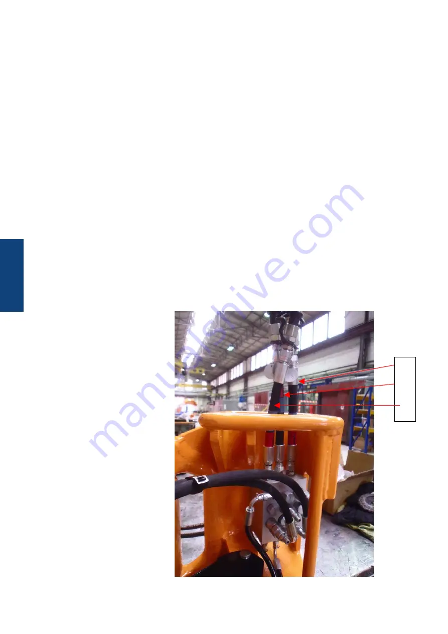
Connecting the hydraulics
The elevator 613000-Y-H-F has three
connections on the rear (A, B and C).
Connection A:
The hydraulic pressure at connection “A“
closes the elevator
Connection B:
The hydraulic pressure at connection “B“
opens the elevator
Connection C:
When the elevator is completely closed
via connection “A”, connection C applies
hydraulic pressure, depending on the
pressure in “A”.
WARNING: b
efoRe
coNNectING
the
hydRAulIc
poWeR
equIpmeNt
to
the
elevAtoR
,
cleAN
All
the
couplINGs
cARefully
.
B
A
C
Installation of the hydraulics
Ensure that the controls are designed in such a way that, after a hydraulic or
electric power black out, the actual situation of the valves doe not change. No
movement in any part of the tool is allowed after the power, either electric or
hydraulic or both, comes up again. The tool and load should always remain in a
safe state.
Ensure that there are valves installed which allow the tool to be insolated between
the hydraulic power rig lines and the tool. This is to prevent to have to shut down
all rig power lines or HPU’s in case of maintenance, emergency or otherwise.
NOTE: The elevator is filled with hydraulic oil at delivery. Ensure it is filled when
installing the elevator.
NOTE: Ensure to purge the air from the elevator before commencing work by
opening and closing the elevator 10 x.
WARNING: e
NsuRe
ANy
hydRAulIc
lINes
fRom
ANd
to
the
elevAtoR
must
be
bouNd
tIGht
to
the
RIG
stRuctuRe
oR
otheRWIse
IN
oRdeR
to
pReveNt
the
hoses
fRom
WhIplAshING
IN
cAse
of
AN
INAdveRt
fAIluRe
/
bReAkING
of
the
hoses
.
Summary of Contents for 613000-Y-H-F
Page 8: ...8 ...
Page 9: ...9 DESCRIPTION DESCRIPTION ...
Page 16: ...16 DESCRIPTION ...
Page 17: ...17 COMMISIONINGS COMMISIONING COMMISSIONING ...
Page 20: ...20 COMMISIONINGS ...
Page 21: ...21 INSTALLATION INSTALLATION ...
Page 27: ...27 OPERATIONS OPERATIONS ...
Page 29: ...29 MAINTENANCE INSPECTION MAINTENANCE INSPECTION ...
Page 43: ...43 SIZE COMPONENTS SIZE COMPONENTS ...
Page 46: ...46 ...
Page 47: ...47 DRAWINGS SPARE PARTS DRAWINGS SPARE PARTS ...
Page 51: ...51 DRAWINGS SPARE PARTS PN 613040 Mechanic Kit D 29 31 D 2 5 31 31 18 3 ...
Page 52: ...52 DRAWINGS SPARE PARTS 570 9 27 7 21 11 4 25 8 1 28 6 22 5 131 87 238 85 23 5 ...
Page 53: ...53 DRAWINGS SPARE PARTS 25 12 25 26 9 24 19 10 30 50 18 23 C 1 2 16 17 13 14 15 ...
Page 62: ...62 DRAWINGS SPARE PARTS ...


